Inspired by the movie “The Fifth Element”
This article summarizes my efforts to create a set of interactive elemental stone replicas based on the iconic props from the movie “The Fifth Element.” I may have been a bit too ambitious, but I wanted the stones to have an authentic look, be relatively cheap, and have some level of interactivity. This project was a great learning opportunity and I’m very please with the final outcome.
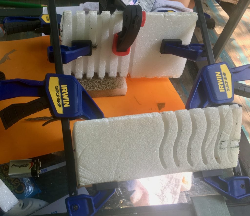
My initial efforts began with hours of scouring the Internet for quality screenshots from the movie. In the process I stumbled upon a variety of like-minded souls which had previously made their own set of elemental stones. There were concrete stones, wooden stones, 3d printed stones, the assortment is nearly endless. There’s even an Instructable. I chose to build my stones from carved rigid styrofoam. This material had a variety of benefits as well as detractors. It was cheap, lightweight and generally easy to work with. The main drawback was its fragility and inability to hold fine carving details. Through trial and error I feel I was able to still make it work.
Supplies
- Styrofoam Boards
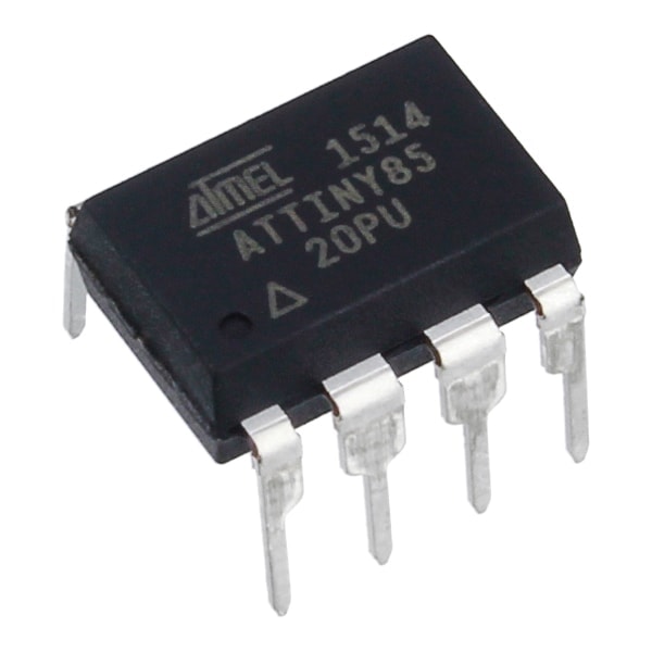
- ATTiny85 Micro-controller
- 8pin IC Sockets DIP IC Sockets Adaptors
- 9V Battery Connector with wires
- Double-sided Prototyping PCB
- DC-DC Buck Converter
- 3-Pin Vertical Slide Switch
- Metal Ball Tilt Switch Sensor
- WS2812B RGB LEDs
- 22 gauge wire in assorted colors
- Ribbon Cable
- Mod Podge Sealer
Tools
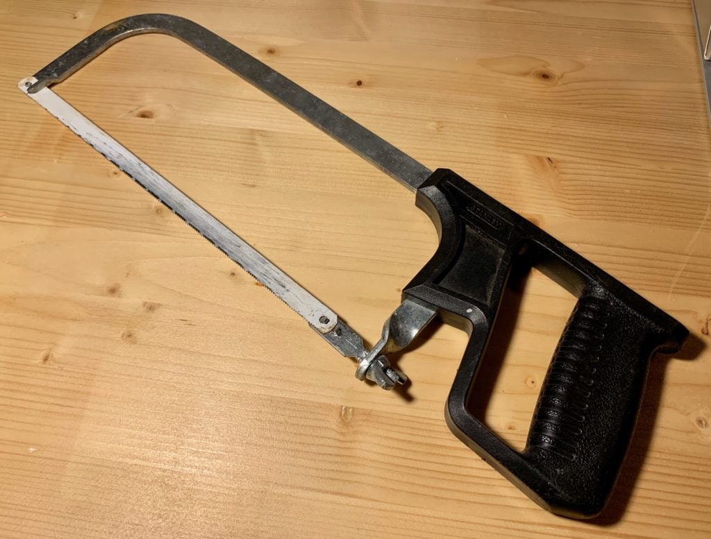
- Hack Saw
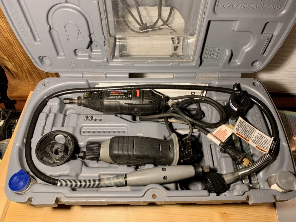
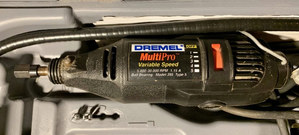
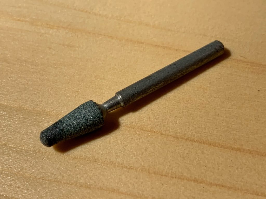
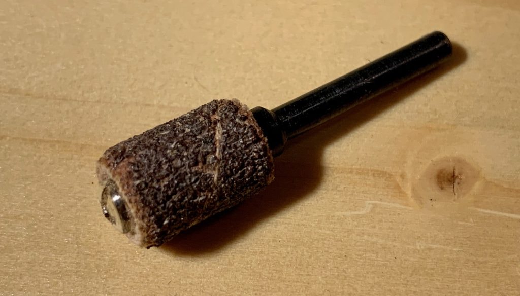
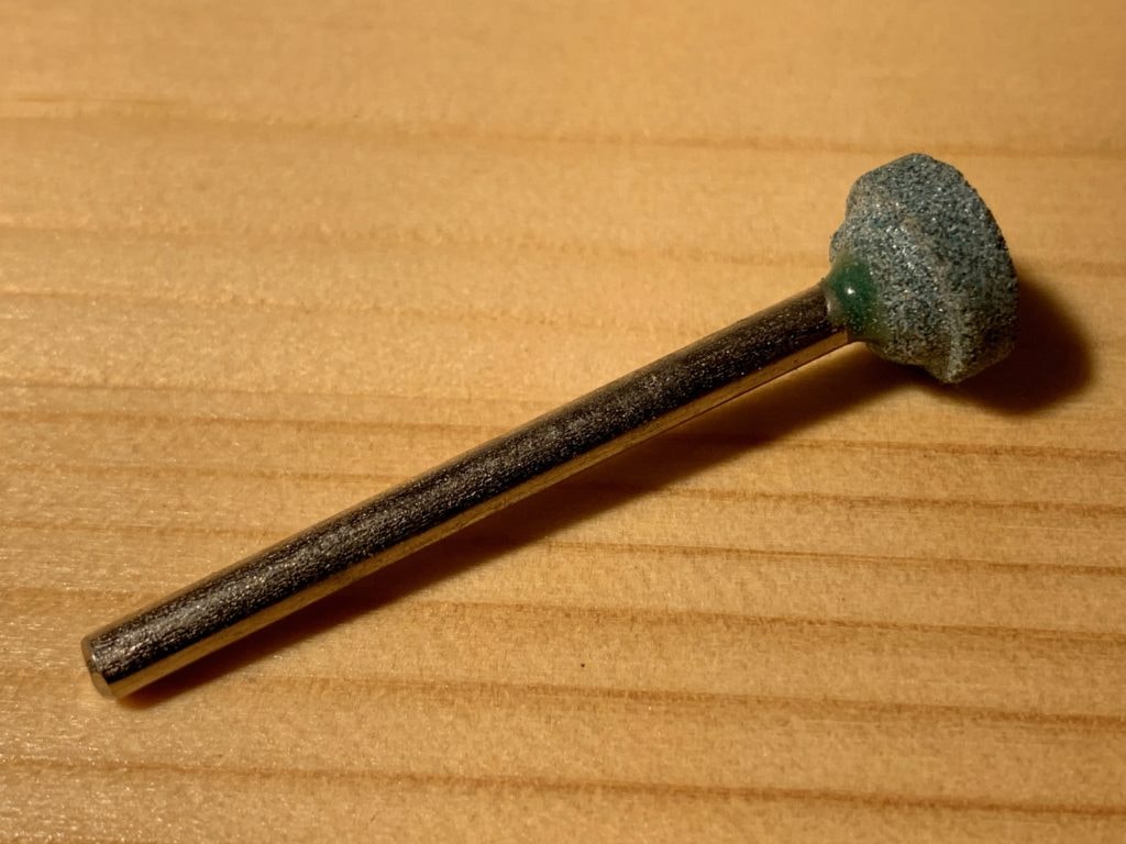
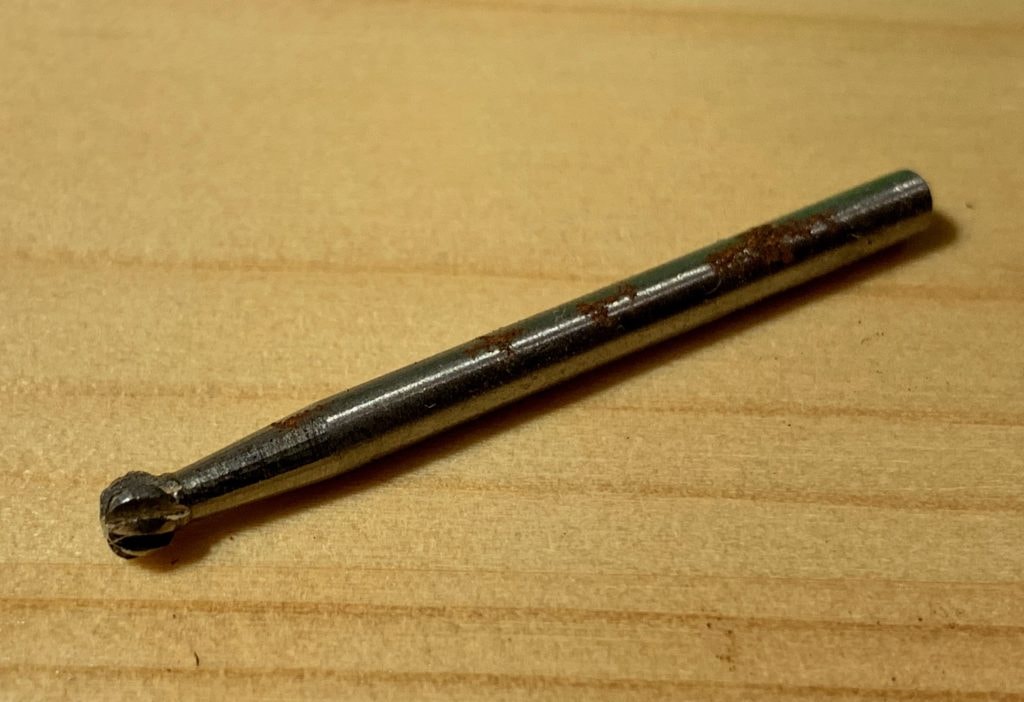
- Dremel with assorted bits
- Soldering Iron with solder
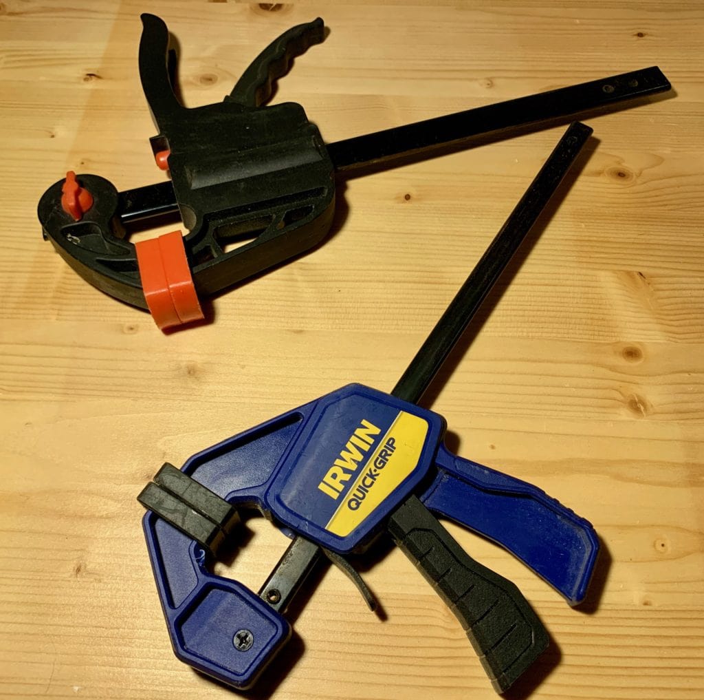
- Assorted clamps
- Paint and paint brushes
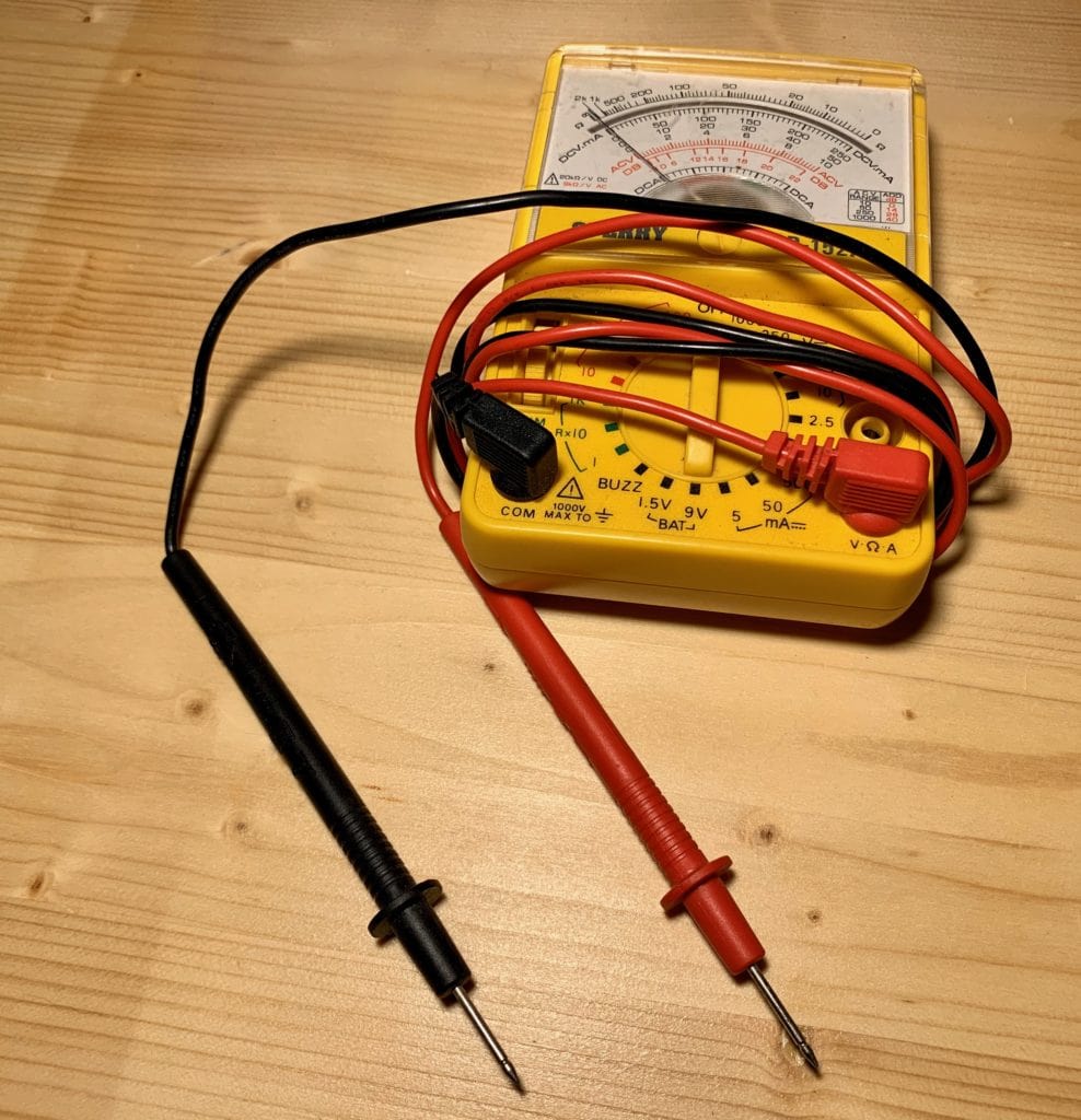
- Multimeter
- AVR Programmer or Arduino
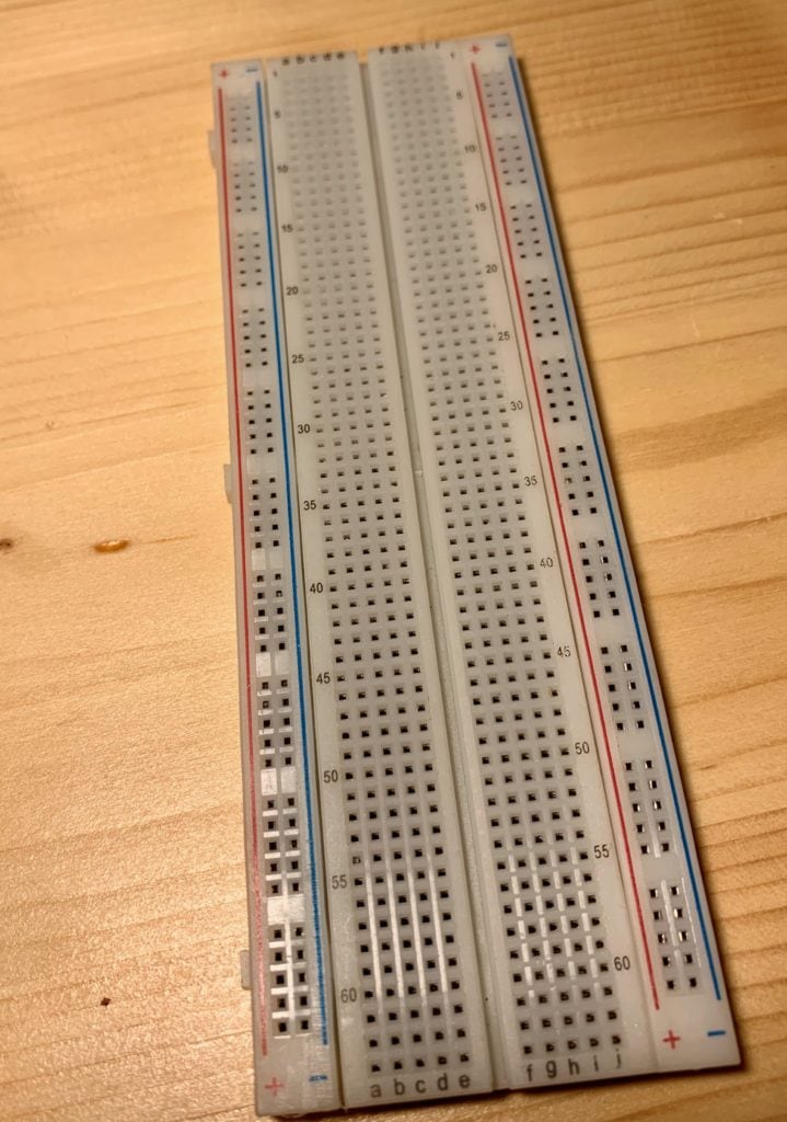
- Large Solderless Breadboard

Best Laid Plans
My initial plans included an Arduino Nano for the brains, three multi-colored LEDs, and three moving flanges driven by a single miniature servo. I was quickly forced to revise my plans because of two big issues.
The first issue arose when I realized that I had underestimated the interior space required for all of the planned components. There just simply wasn’t going the be enough space for an Arduino Nano, a servo (plus linkage), the LEDs and a 9V battery.
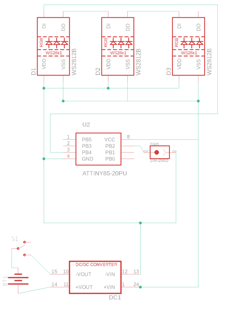
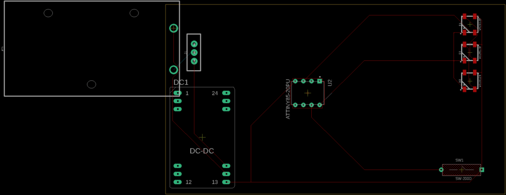
The second issue involved the non-durable nature of styrofoam. To reduce the space requirements, I decided to eliminate the miniature servo, permanently fix the flanges, and use a custom board with an ATTiny85 as the brains. This freed up a good bit of interior space and eliminated the potential wear and tear on the flanges.
Part 1 - Preparing the Stone Structures
FloraCraft Foam Block 1.8 Inch x 11.8 Inch x 17.8 Inch White
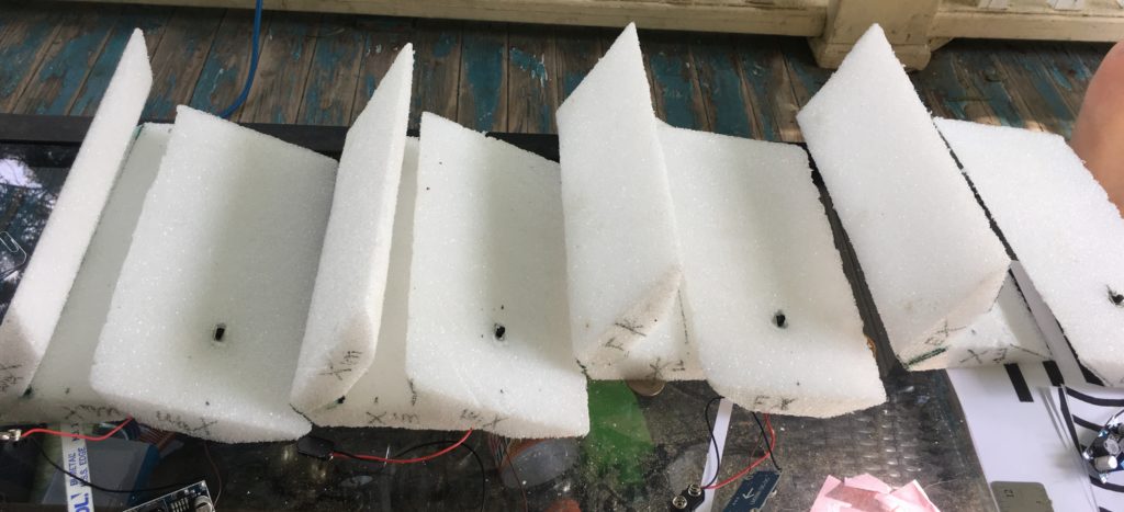
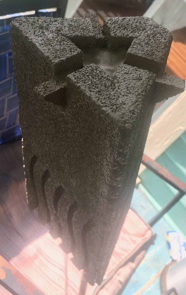
Based on the relative proportions of the stones in the movie, I made a best-guess estimate of the dimensions. Each stone has two short side and one long side in the back. All three sides start out the same size but because the front edge of the triangle is flattened two of the sides end of shorter. I cut the rigid foam boards into 12 equal rectangles of … dimensions. Each of the stones will start out as equilateral triangles so my next step was to cut the lengthwise edges at approximately 30 degree angles so that the three sides would butt together cleanly.
The First Seams
I then split the sides into four equal groups and tweaked the joints within each set so that they were custom fitted to one another. The fate of each side had been decided. I labeled the bottom of each side to indicate which side of which stone each piece was. I glued the front edge of each stone together using white glue and Mod Podge. While drying, the three sides were held together using rubber bands to ensure the joint dried at the correct angle. After the front joint was cured, I used a hack saw, several small files, and a razor blade to trim down the front corner to give it its blunted appearance. This was a very messy and poorly planned task. Looking back I should have just used a hot wire to cleanly cut the foam… oh well.
The Power Switch
Unassembled stone sides with two position power switch and battery connector installed.
Next I began the task of installing the power switch. I used the Dremel with a drill bit to punch a small hole through the center of the back side. Once the hole was drilled I also cleared a small cavity to house the power switch. I fed the power leads and battery connector wires through the hole and soldered them to the switch. I then pulled back the excess wire and glued the switch housing into the foam cavity which had been cut for it. This could prove problematic if I ever have to replace one of these switches in the future.
The final portion of the stone bodies to be completed was the three flanges located at the top center of each side. After measuring and cutting the flanges from the sides I also tapered the back edge to a point that looked right. This was very tedious work because the small foam flanges were very fragile and at this point I was very please I had chosen not to make them move. I positioned them as best as possible and glued them in place. I was especially generous with the glue around the flanges to give them some additional structural support.
Part 2a - Prototyping the Electronic Internals
After the stone bodies were prepped, I spent a couple of days tinkering and prototyping the internal electronics. I decided that each stone would have a main power switch, three multi-colored LEDs, and an internal ball tilt switch to change the LED mode. The LEDs have an element mode, a rainbow mode, a disco mode, and high/med/low lamp mode.
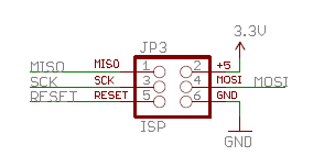
I don’t own an actual AVR programmer so throughout this project I was using one of my many Arduino Nano boards as an ISP programmer to get my code onto the ATTiny85 chips. You can see the programming headers I added to the water stones main board. I didn’t like this arrangement and that is why I chose to make the microprocessor removable in the other three stones. Overall I was very please with how well the Arduino Nano worked as a programmer. I’ll probably continue ising this setup for future projects.
The Code
Below is the code I loaded onto each of the ATTiny85 microcontrollers. Each stone had a slight modification to adjust for the the particular elemental color of that stone.
#include <Adafruit_NeoPixel.h>
//#include <avr/power.h>
//#include <avr/sleep.h>
//#include <avr/io.h>        // Adds useful constants
//#include <util/delay.h>    // Adds delay_ms and delay_us functions
//#include <avr/wdt.h>

const int SERVO_PIN = 0;
const int SWITCH_PIN = 2;
const int PIXEL_PIN = 4;

//Modes
const int STONE_MODE = 0;
const int RAINBOW_MODE = 1;
const int COLOR_WIPE = 2;
const int THEATER_CHASE = 3;
const int LAMP_100 = 4;
const int LAMP_75 = 5;
const int LAMP_50 = 6;
const int LAMP_25 = 7;

volatile int pixelMode = 0;

volatile boolean interrupted = false;
unsigned long startMillis;
unsigned long currentMillis;
const unsigned long MODE_SWITCH_DELAY = 1500;

const byte ledPin = 13;
volatile int counter = 0;
//bool previousSwitch = false;


Adafruit_NeoPixel pixels = Adafruit_NeoPixel(3, PIXEL_PIN, NEO_GRB + NEO_KHZ800);

uint32_t blue = pixels.Color(0, 0, 255);
uint32_t red = pixels.Color(255, 0, 0);
uint32_t green = pixels.Color(0, 255, 0);
uint32_t yellow = pixels.Color(255, 100, 0);

void setup() {
  //Serial.begin(9600);
  //Serial.println("Booting...");
  //ADCSRA &= ~(1<<ADEN);
  //setup_watchdog(8); // approximately 0.5 seconds sleep
  pinMode(SWITCH_PIN, INPUT_PULLUP);
  attachInterrupt(0, changeMode, RISING);
  pixelMode = STONE_MODE;
  pixels.begin();
  pixels.show();
}

void loop() {
  switch (pixelMode) {
    case STONE_MODE: //0
      stone();
      break;
    case RAINBOW_MODE: //1
      rainbow(20);
      rainbowCycle(20);
      break;
    case COLOR_WIPE: //2
      colorWipe(pixels.Color(255, 0, 0), 50); // Red
      colorWipe(pixels.Color(0, 255, 0), 50); // Green
      colorWipe(pixels.Color(0, 0, 255), 50); // Blue
      break;
    case THEATER_CHASE: //3
      theaterChase(pixels.Color(127, 127, 127), 50); // White
      theaterChase(pixels.Color(127, 0, 0), 50); // Red
      theaterChase(pixels.Color(0, 0, 127), 50); // Blue
      break;
    case LAMP_100: //4
      lamp(100);
      break;
    case LAMP_75: //5
      lamp(75);
      break;
    case LAMP_50: //6
      lamp(50);
      break;
    case LAMP_25: //7
      lamp(25);
      break;
  }
  interrupted = false;

}

void changeMode() {
  currentMillis = millis();  //get the current "time" (actually the number of milliseconds since the program started)
  if (currentMillis - startMillis >= MODE_SWITCH_DELAY) {
      interrupted = true;
      pixelMode = pixelMode + 1;
      if (pixelMode > 7) {pixelMode = 0;}
      startMillis = currentMillis;
  }
}

//void sleep() {
//  ADCSRA &= ~_BV(ADEN);                   // ADC off
//  set_sleep_mode(SLEEP_MODE_PWR_DOWN);    // replaces above statement
//  sleep_enable();                         // Sets the Sleep Enable bit in the MCUCR Register (SE BIT)
//  sleep_cpu();                            // sleep
//  sleep_disable();                        // Clear SE bit
//  ADCSRA |= _BV(ADEN);                    // ADC on
//} // sleep

void colorWipe(uint32_t c, uint8_t wait) {
  for(uint16_t i=0; i<pixels.numPixels(); i++) {
    pixels.setPixelColor(i, c);
    pixels.show();
    delay(wait);
  }
}

void rainbow(uint8_t wait) {
  uint16_t i, j;

  for(j=0; j<256; j++) {
    for(i=0; i<pixels.numPixels(); i++) {
      pixels.setPixelColor(i, Wheel((i+j) & 255));
    }
    pixels.show();
    delay(wait);

    if (interrupted == true){break;}
  }
}

// Slightly different, this makes the rainbow equally distributed throughout
void rainbowCycle(uint8_t wait) {
  uint16_t i, j;

  for(j=0; j<256*5; j++) { // 5 cycles of all colors on wheel
    for(i=0; i< pixels.numPixels(); i++) {
      pixels.setPixelColor(i, Wheel(((i * 256 / pixels.numPixels()) + j) & 255));
    }
    pixels.show();
    delay(wait);
    if (interrupted == true){break;}
  }
}

//Theatre-style crawling lights.
void theaterChase(uint32_t c, uint8_t wait) {
  for (int j=0; j<10; j++) {  //do 10 cycles of chasing
    for (int q=0; q < 3; q++) {
      for (uint16_t i=0; i < pixels.numPixels(); i=i+3) {
        pixels.setPixelColor(i+q, c);    //turn every third pixel on
      }
      pixels.show();

      delay(wait);

      for (uint16_t i=0; i < pixels.numPixels(); i=i+3) {
        pixels.setPixelColor(i+q, 0);        //turn every third pixel off
      }
      if (interrupted == true){break;}
    }
  }
}

//Theatre-style crawling lights with rainbow effect
void theaterChaseRainbow(uint8_t wait) {
  for (int j=0; j < 256; j++) {     // cycle all 256 colors in the wheel
    for (int q=0; q < 3; q++) {
      for (uint16_t i=0; i < pixels.numPixels(); i=i+3) {
        pixels.setPixelColor(i+q, Wheel( (i+j) % 255));    //turn every third pixel on
      }
      pixels.show();

      delay(wait);

      for (uint16_t i=0; i < pixels.numPixels(); i=i+3) {
        pixels.setPixelColor(i+q, 0);        //turn every third pixel off
      }
      if (interrupted == true){break;}
    }
  }
}

// Input a value 0 to 255 to get a color value.
// The colours are a transition r - g - b - back to r.
uint32_t Wheel(byte WheelPos) {
  WheelPos = 255 - WheelPos;
  if(WheelPos < 85) {
    return pixels.Color(255 - WheelPos * 3, 0, WheelPos * 3);
  }
  if(WheelPos < 170) {
    WheelPos -= 85;
    return pixels.Color(0, WheelPos * 3, 255 - WheelPos * 3);
  }
  WheelPos -= 170;
  return pixels.Color(WheelPos * 3, 255 - WheelPos * 3, 0);
}
void stone() {
  float i, in, p0, p1, p2;
  pixels.setBrightness(128);
  for (int i = 0; i < 4; i++) {
    for (in = 0; in < 6.283; in = in + 0.01) {
        p0 = sin(in - PI) * 127.5 + 127.5;
        p1 = sin(in - PI / 2) * 127.5 + 127.5;
        p2 = sin(in) * 127.5 + 127.5;
        //Wind (Yellow)
        pixels.setPixelColor(0, .4 * p0, p0, 0);
        pixels.setPixelColor(1, .4 * p1, p1, 0);
        pixels.setPixelColor(2, .4 * p2, p2, 0);
        //Earth (Green)
        //pixels.setPixelColor(0, p0, 0, 0);
        //pixels.setPixelColor(1, p1, 0, 0);
        //pixels.setPixelColor(2, p2, 0, 0);
        //Water (Blue)
        //pixels.setPixelColor(0, 0, 0, p0);
        //pixels.setPixelColor(1, 0, 0, p1);
        //pixels.setPixelColor(2, 0, 0, p2);
        //Fire (Red)
        //pixels.setPixelColor(0, 0, p0, 0);
        //pixels.setPixelColor(1, 0, p1, 0);
        //pixels.setPixelColor(2, 0, p2, 0);

        pixels.show();
      if (interrupted == true){break;}
    }
  }
  //Wind (Yellow)
  pixels.setPixelColor(0, 100, 255, 0);
  pixels.setPixelColor(1, 100, 255, 0);
  pixels.setPixelColor(2, 100, 255, 0);
  //Earth (Green)
  //pixels.setPixelColor(0, 255, 0, 0);
  //pixels.setPixelColor(1, 255, 0, 0);
  //pixels.setPixelColor(2, 255, 0, 0);

  pixels.show();
  //delay(5000);
  //sleep();
}
void lamp(int brightness) {
  int i;
  pixels.setBrightness(brightness);
  ColorSet(pixels.Color(255, 255, 255));
  //delay(5000);
  //sleep();
}
// Set all pixels to a color (synchronously)
void ColorSet(uint32_t color)
{
    for (int i = 0; i < pixels.numPixels(); i++)
    {
        pixels.setPixelColor(i, color);
    }
    pixels.show();
}
Part 2b - The Guinea Pig
I started the first prototype on a breadboard and once I felt I had most of the kinks worked out I started to assemble the first stone. The internals consist of four main segments, the battery, power board, main board, and LED mast. The water stone was definitely the guinea pig of the set. I made a variety of improvements to the other three stones after lessons learned from the water stone.
For example, the water stone LEDs were connected and supported by a mess of stiff wires. In the other stones I chose to mount them on a horizontal triangular piece of prototype PCB. Also, microcontroller for the water stone is soldered directly to the main board. In the other stones I chose to use an 8-pin DIP IC socket to give me the option to easily reprogram a stone. The water stone looks like a mess on the insides but it works just as well as the other three. After all of this, I was quite pleased to have an ugly white “stone” glowing in my hand.
Part 3 - Carving the Stones
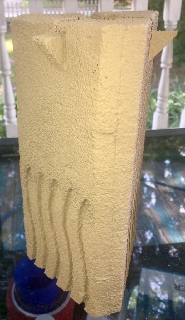
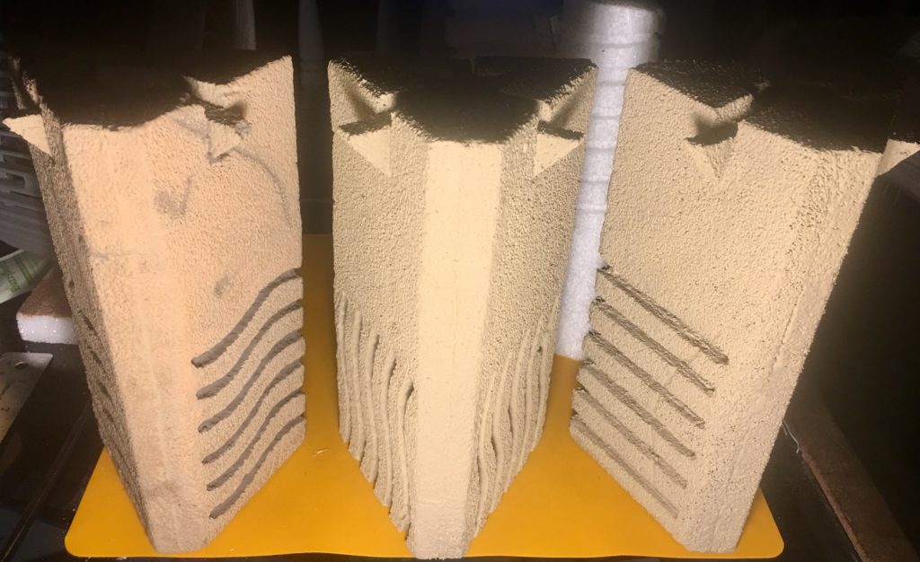
Carving the element symbols onto the stones proved to be much more time consuming than I had anticipated. I saved this step until after the electronics were complete for fear of damaging the patterns. After a some experimentation on some scrap foam I found that the best way to create the marking was by using the Dremel again with a conical sanding bit. I printed the patterns shown below and temporarily attached them to the sides using a light touch of spray adhesive. This way I was able to carve away the black areas and then peel off the remaining white paper. I had to make a few slight adjustment to the pattern to accommodate the power switch but the pattern changes are nearly imperceptible especially after painting.
Part 4 - Assembling the Stones
I could finally finish the assembly process. I attached the electronics to the interior of the back side and then the front V on top. After double checking the position of the electronics and the fitting of the edges, I began glueing the two rear seams on each of the stones. I held the completed bodies together using a variety of C-Clamps and left them to dry for a day or so.
Two of four stones being assembled. The back side was glued in place and held in place with c-clamps.
Part 5 - Priming and Painting the Stones
Fire stone on drying stick after first coat of dark primer. The un-primed foam allowed a colored glow to emanate from the entire stone. A dark primer was used as the first coat after sealing to minimize the bleed-through of light.
The stones were now assembled and I was eager to begin painting. Before paining however I decided to seal the entire outer surface of the stones using Mod Podge. I wanted to make the foam surface less porous and reduce the amount of paint that was going to get absorbed into the foam. This technique worked well and it also gave the stones a much firmer feeling when held in your hand. In my earlier test of the electronics I realized the white foam allowed a great deal of LED light out across the entire stone body. I didn’t want the entire stone glowing so I chose to first prime the stones with a dark tan color to reduce the amount of light that was bleeding through the sides. Next, I applied a lighter sandy color over the dark primer.
The main paint was also applied in several layers. I started with a base color that was as close to movie authentic as possible. I then added slight variations of the base color to create a more natural “stony” feel. The symbol grooves were inset with a very dark grayish tan. As the final paint step I used shadow and highlight effects to create the illusion of cracks, blemished, and other wear marks.
Part 6 - The Final Product!
After several weeks of effort, I finally had all four stones finished. As some finishing touches I decided to create foam caps for the tops and bottom as well a stand to display them on. The white caps on top help soften and diffuse the LEDs and the black cap in the bottom acts as a battery holder.
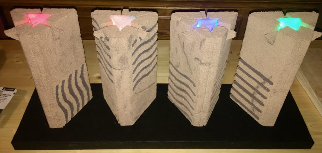
The display stand is another piece of rigid foam. The stand has four shallow insets custom fitted to each of the stones. The entire based was lined with flat black felt. The felt was attached using spray adhesive on the large surfaces and a tiny bit of super glue on the corners and inset seams.
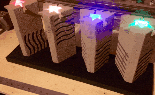
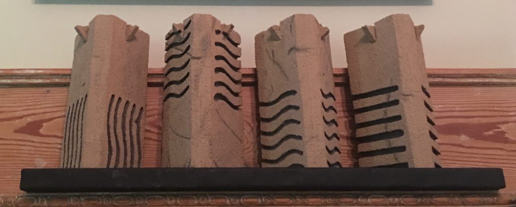
I hope you like the way they turned out, I certainly do. They look amazing on my fireplace mantle.
Completed Elementa Stone Replica Set on Fireplace Mantle.