Brand: RadioShack
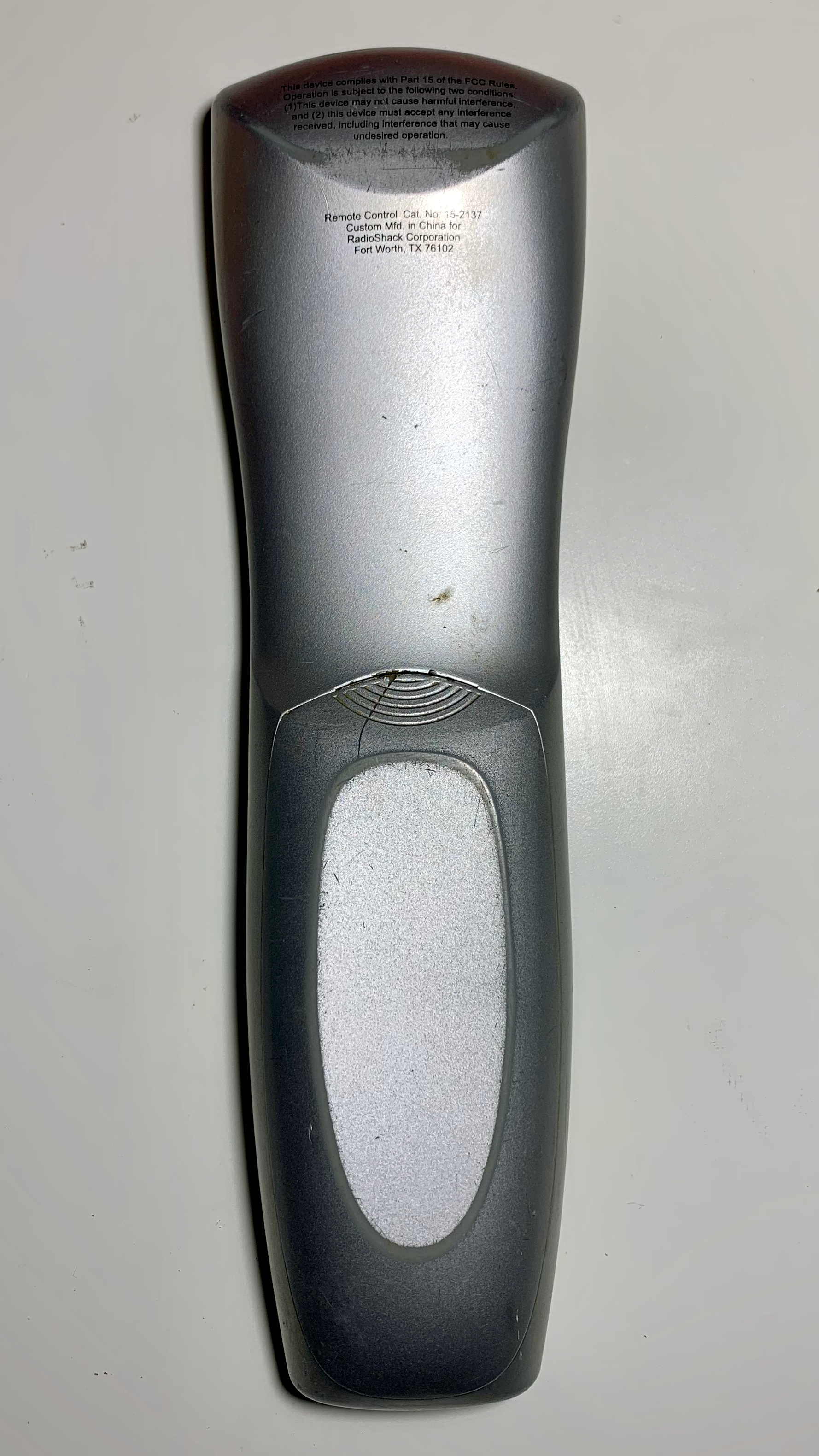
Model: 15-2137
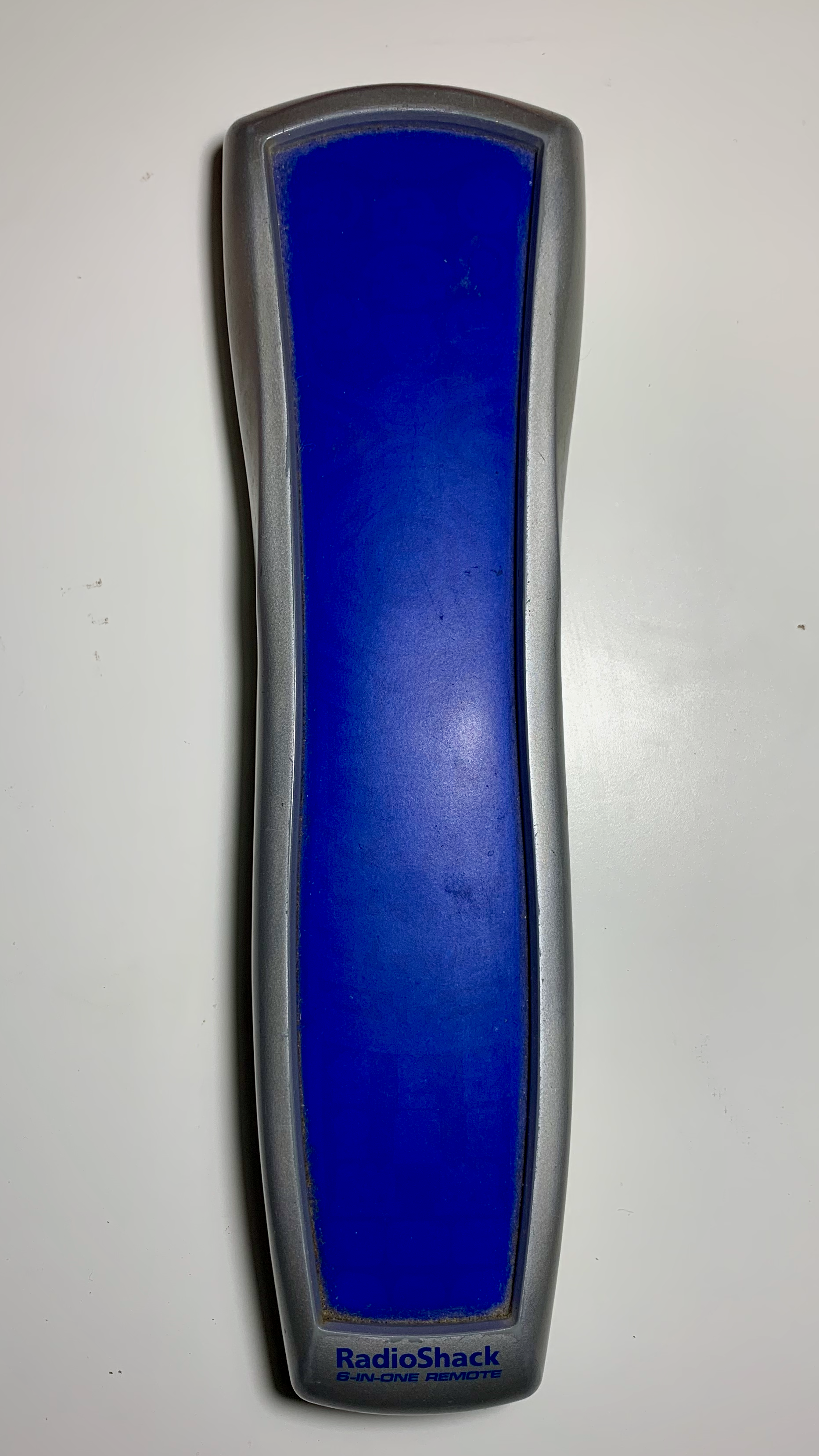
Name: Kameleon 6-in-1 Universal Remote
This was a very unique universal remote to own. This remote could control up to six (6) devices and was able to adapt it’s button display to match the selected device. The buttons were individually lit which made finding the right button in a dark room a simple task.
Exterior
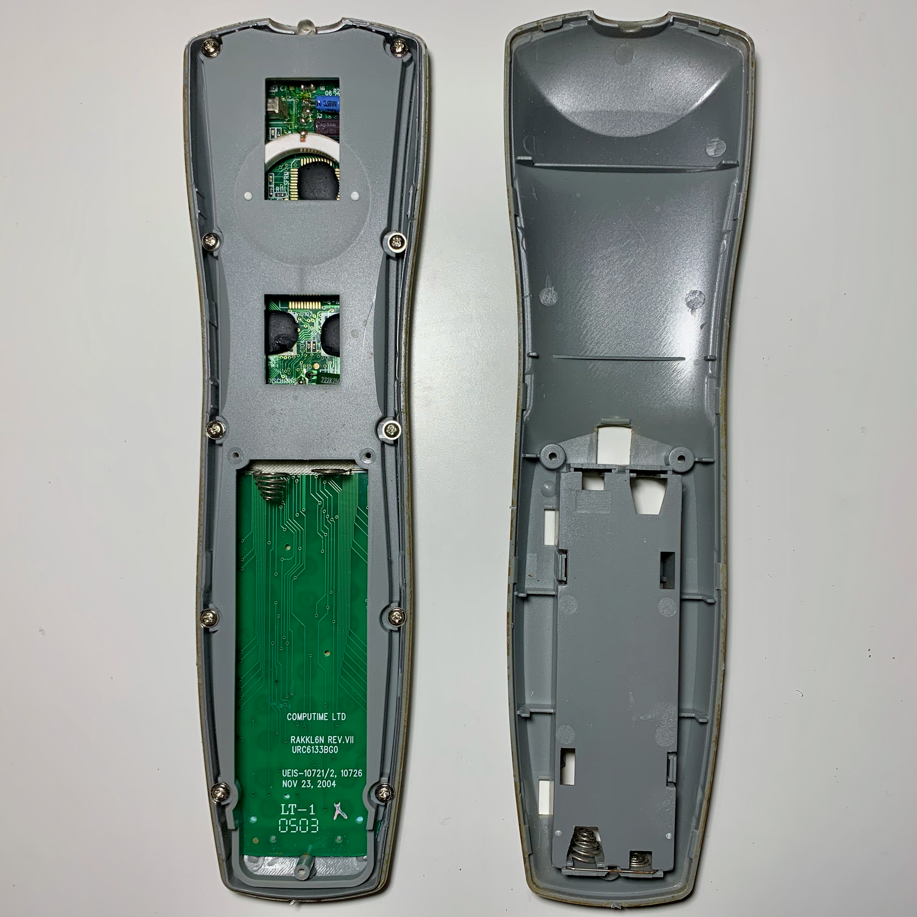
Interior
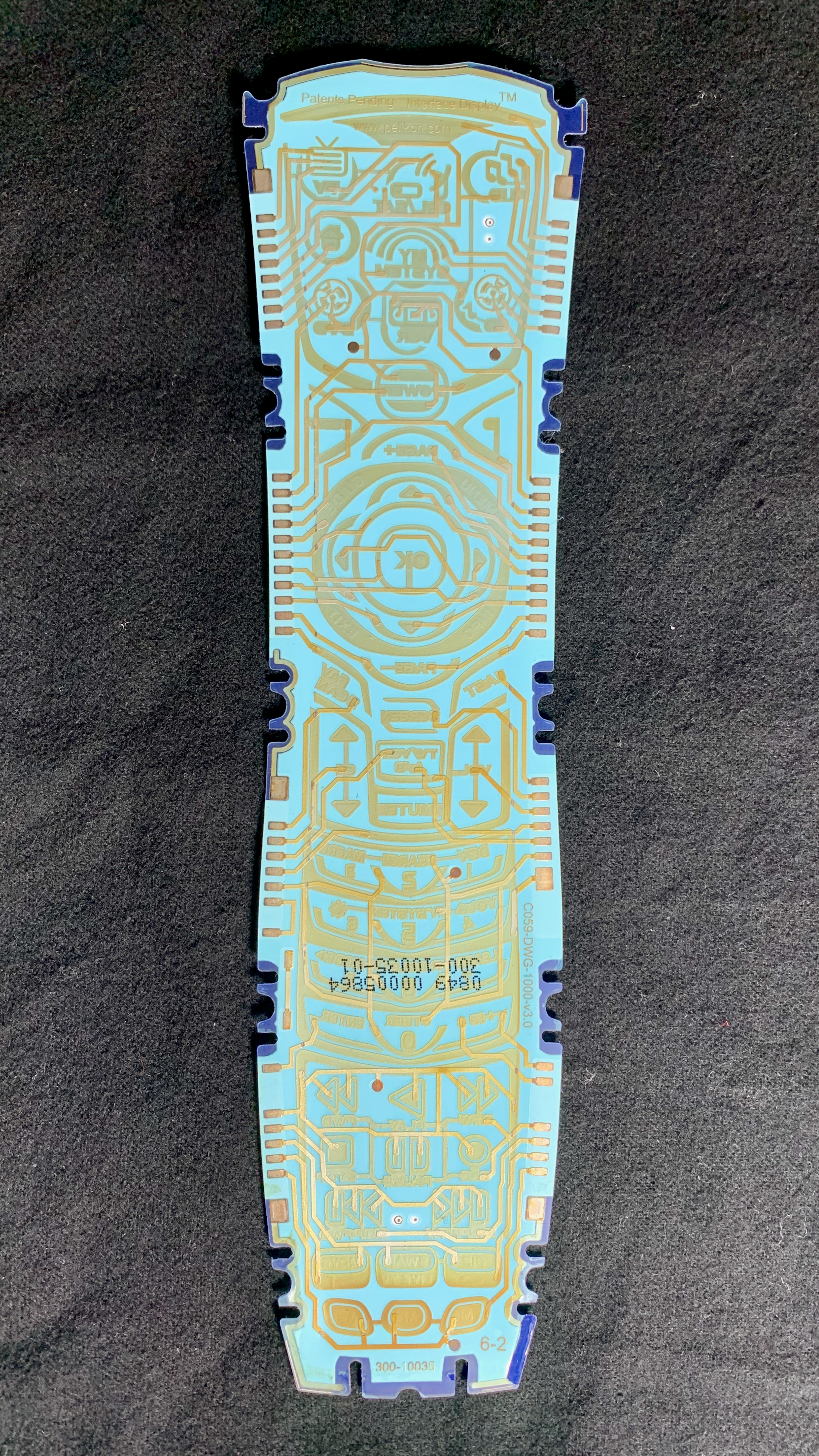
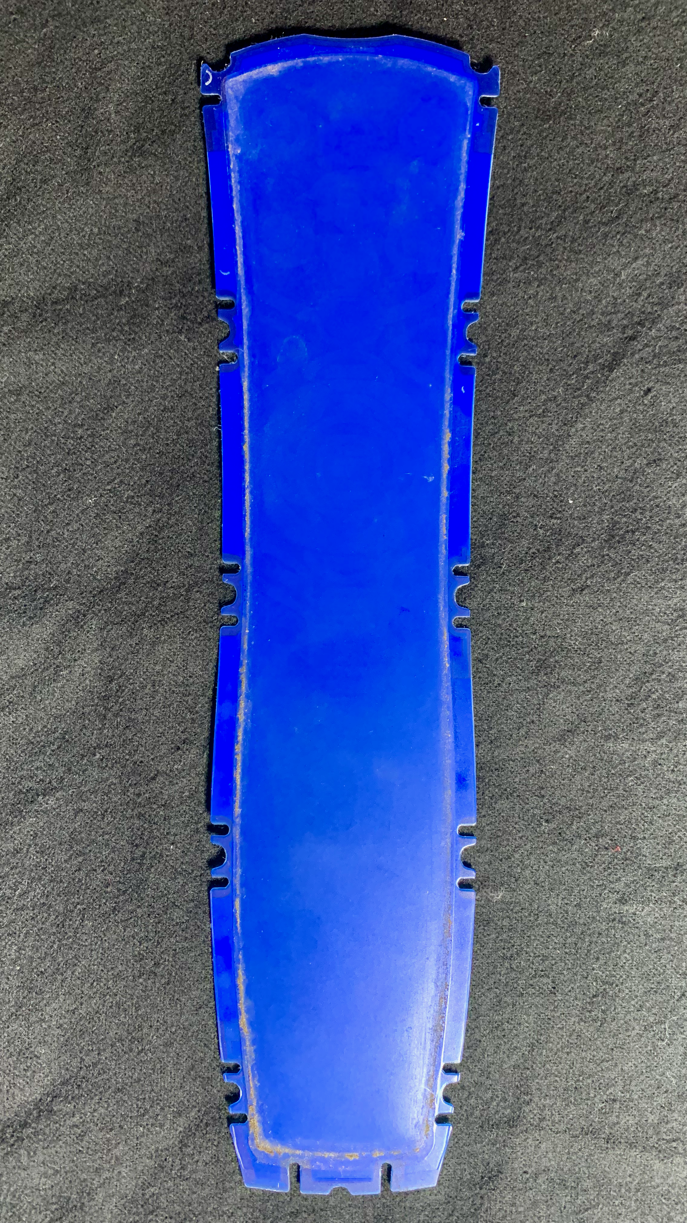
Display Panel
The remotes unique button design was simultaneously it’s best feature and it’s greatest flaw. The active buttons were lit using an electoluminecent panel. This effectively allowed the remote to hide buttons that were not currently active. Unfortunately, this also meant that the remote consumed power whenever the buttons were visible. The remote tried to conserve power by only showing the buttons for a brief period of time. To display the buttons, the user could shake the remote which would active a ball switch and cause the keys to light up.
However, even with this feature this remote took four AA batteries and would consume them rather quickly. I don’t think I’ve had any other device that has gone through batteries as quickly as this remote.
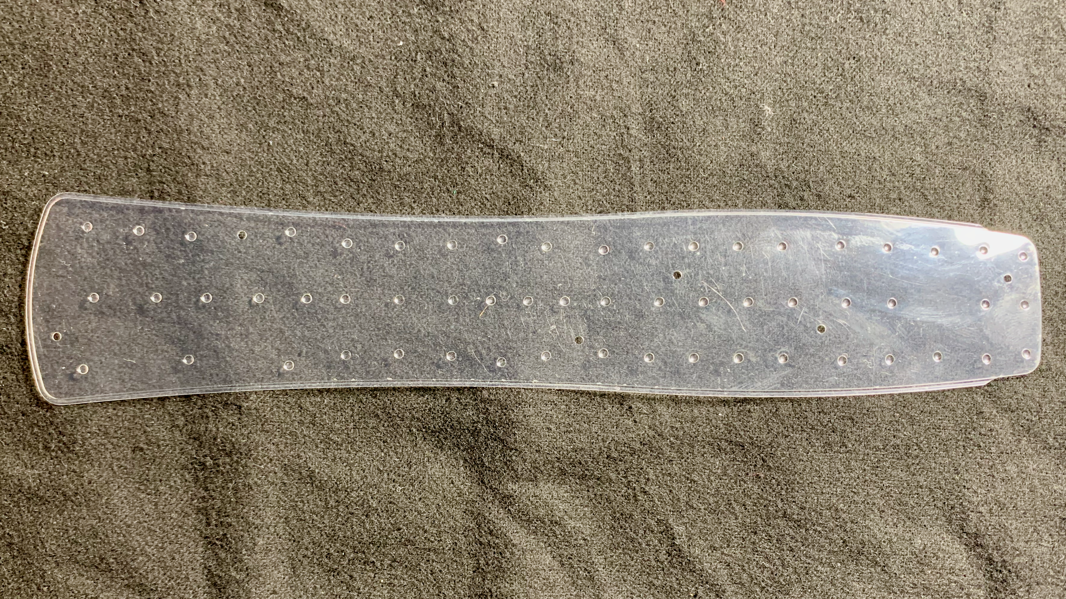
Button Membrane
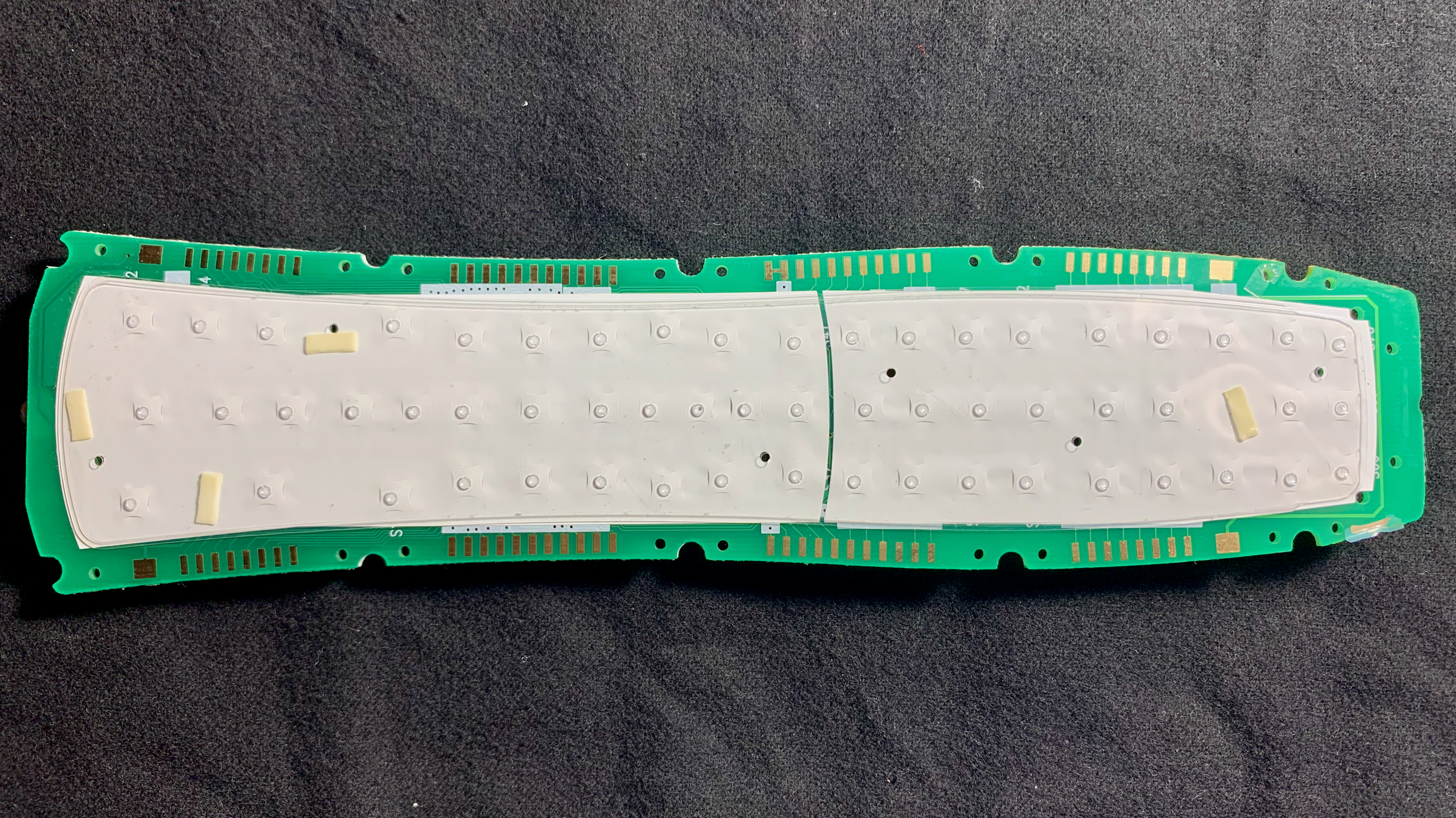
The button mechanics rely on a two membrane layers. The top layer is a soft plastic with small plastic bumps located at each button position.
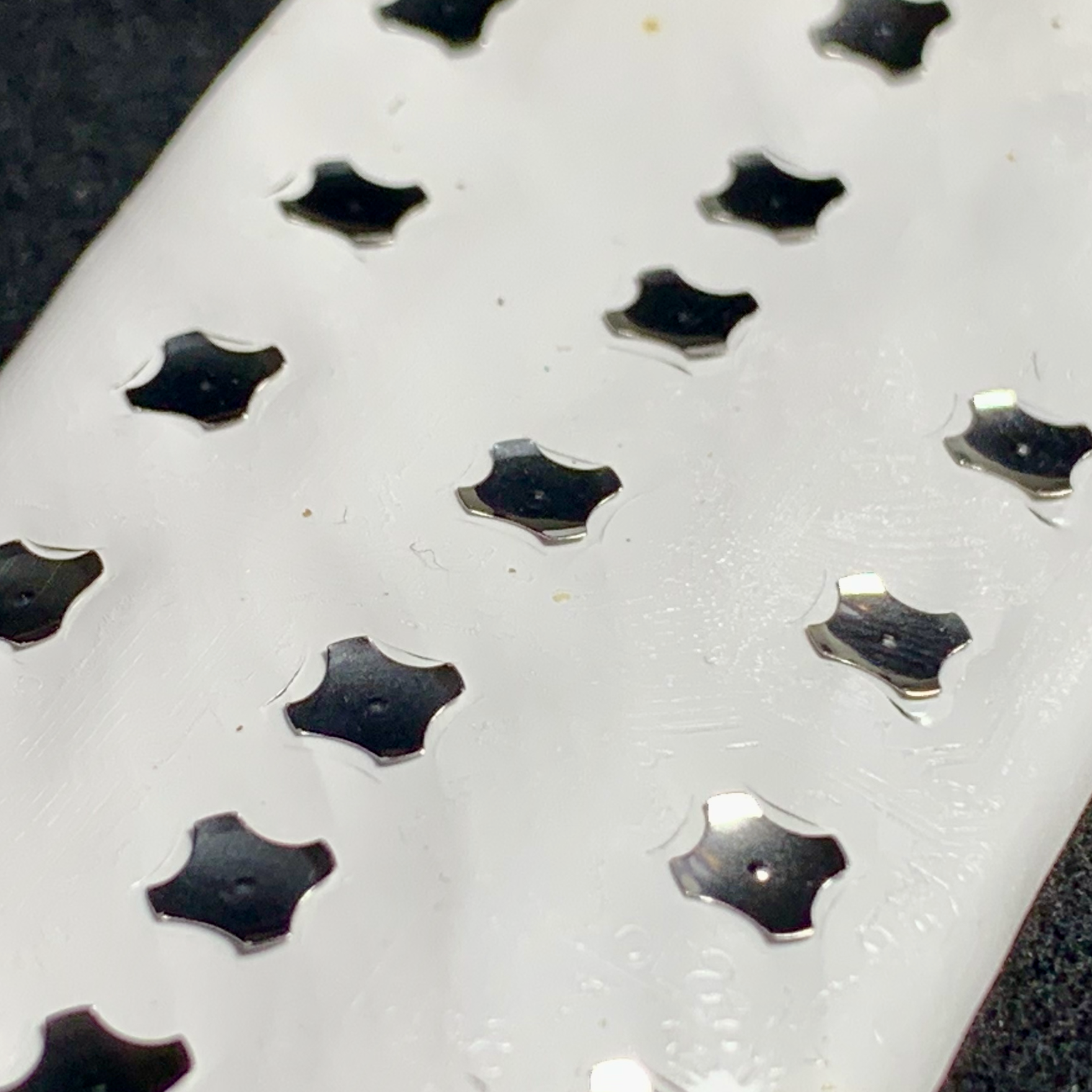
The bottom membrane layer was comprised of a thin sheet of plastic adhesive which held a series small dome shaped metal clips in place over the button contacts on the circuit board. When the user presses a button, the bump from the top layer would depress the center of the corresponding metal clip. The metal clip would buckle and complete the circuit between the contacts. Once pressure was release, the metal clip would snap back into its original shape.
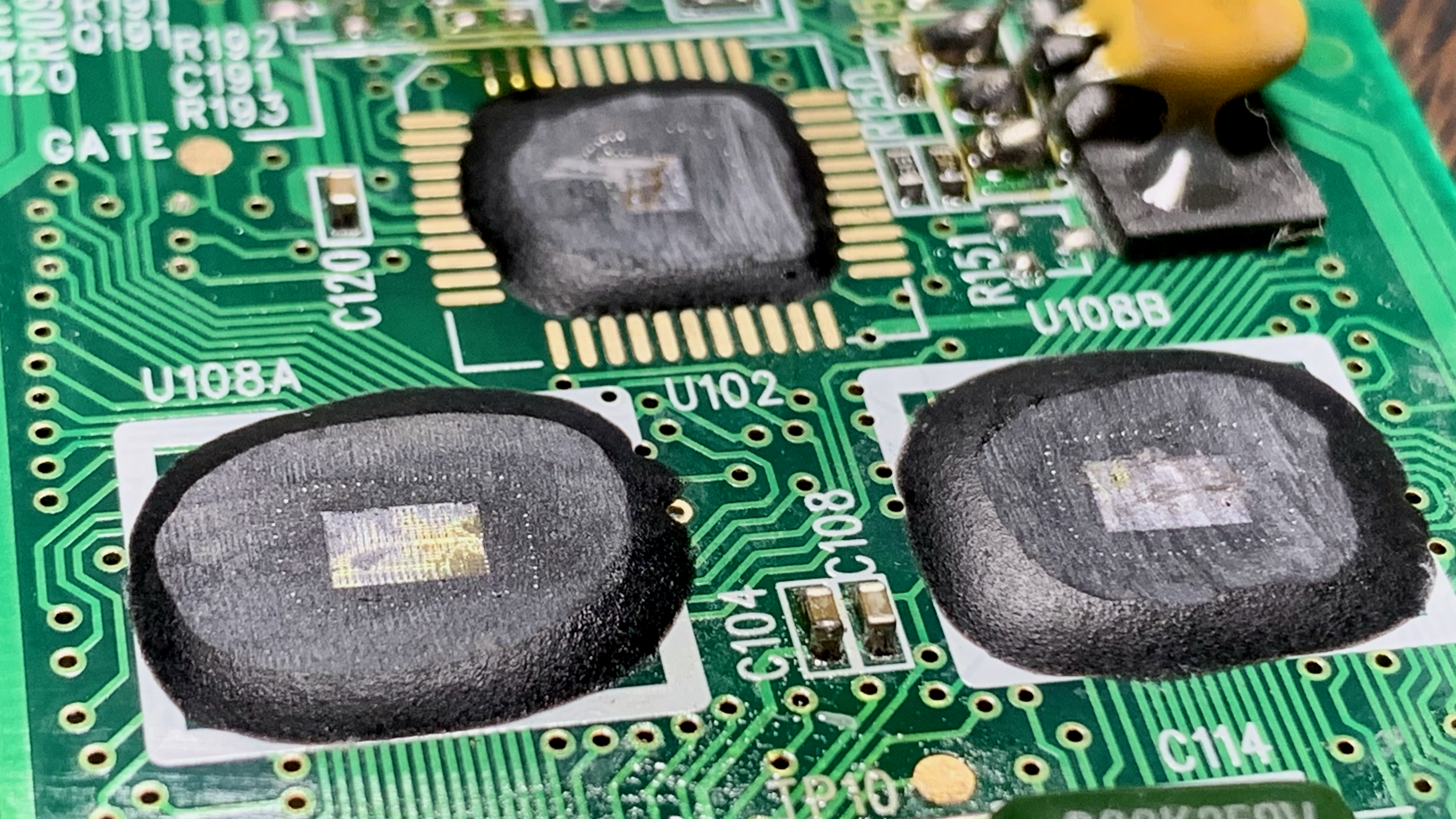
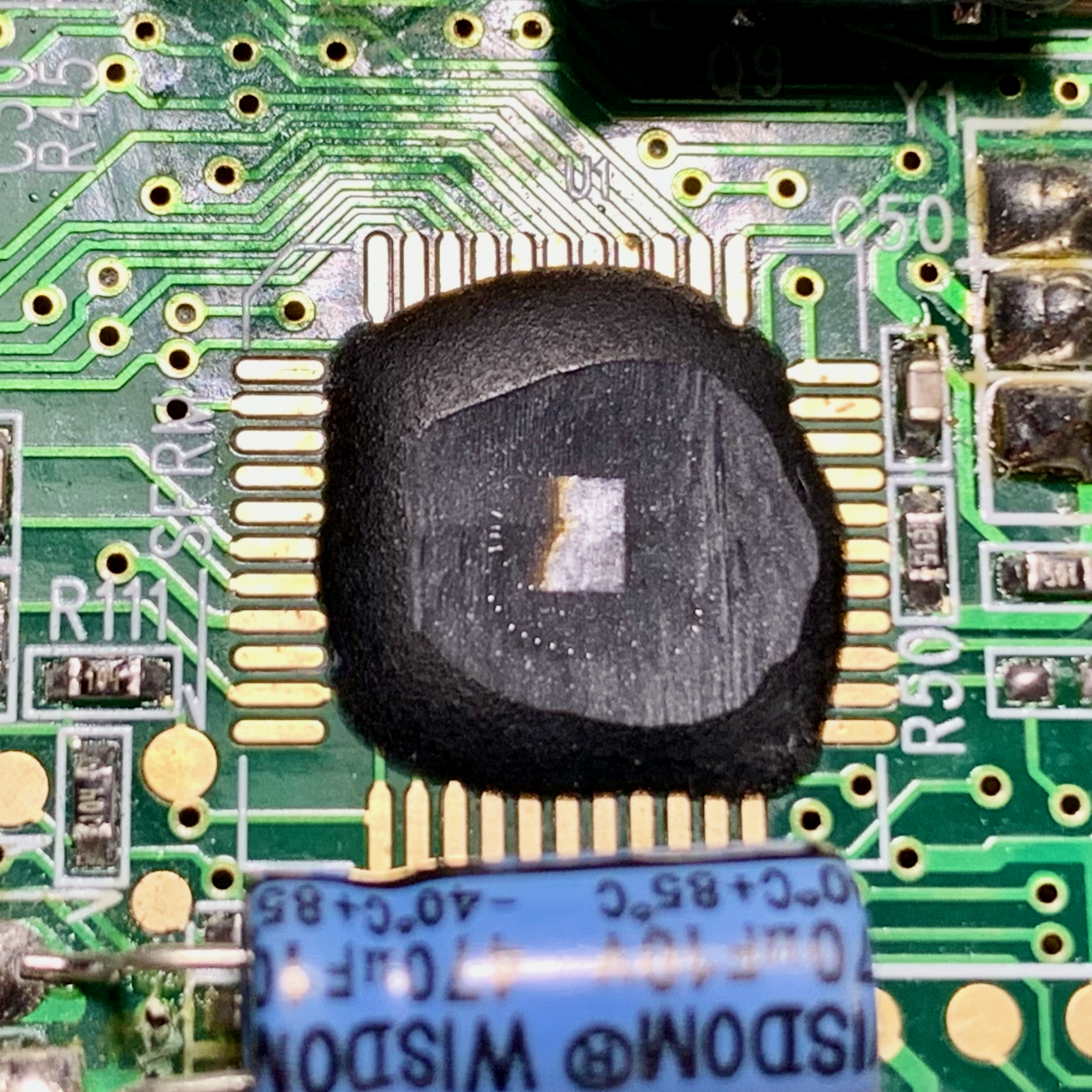
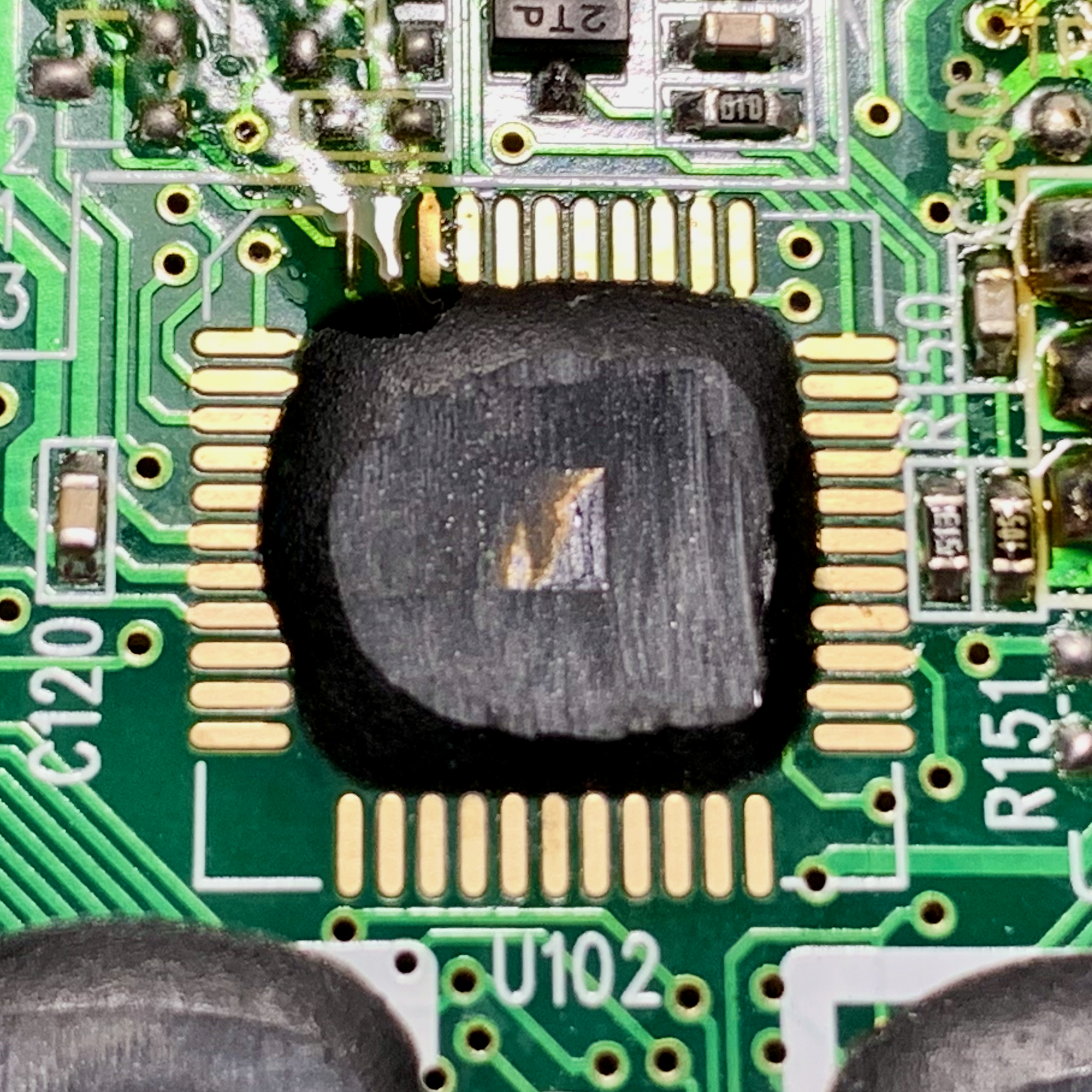
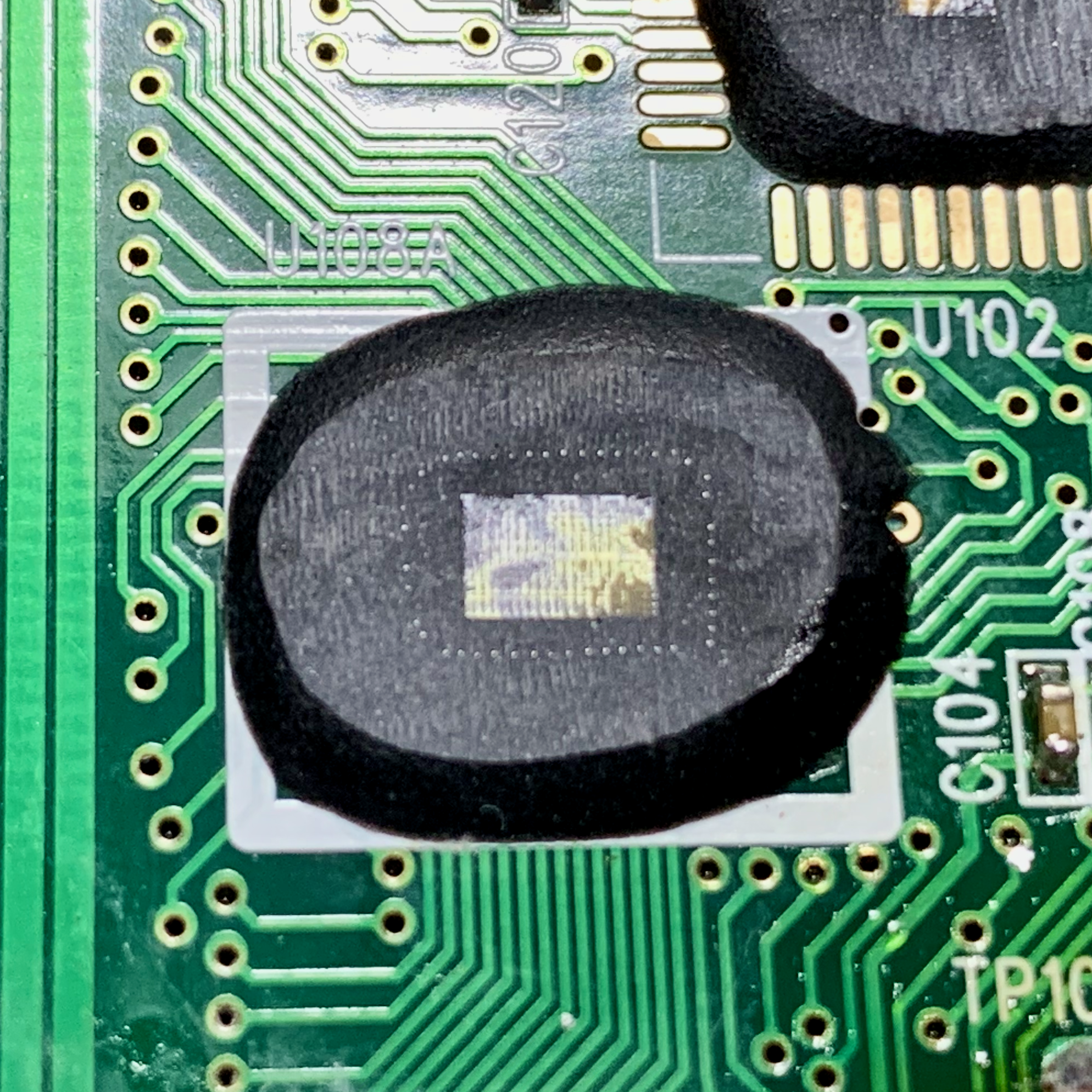
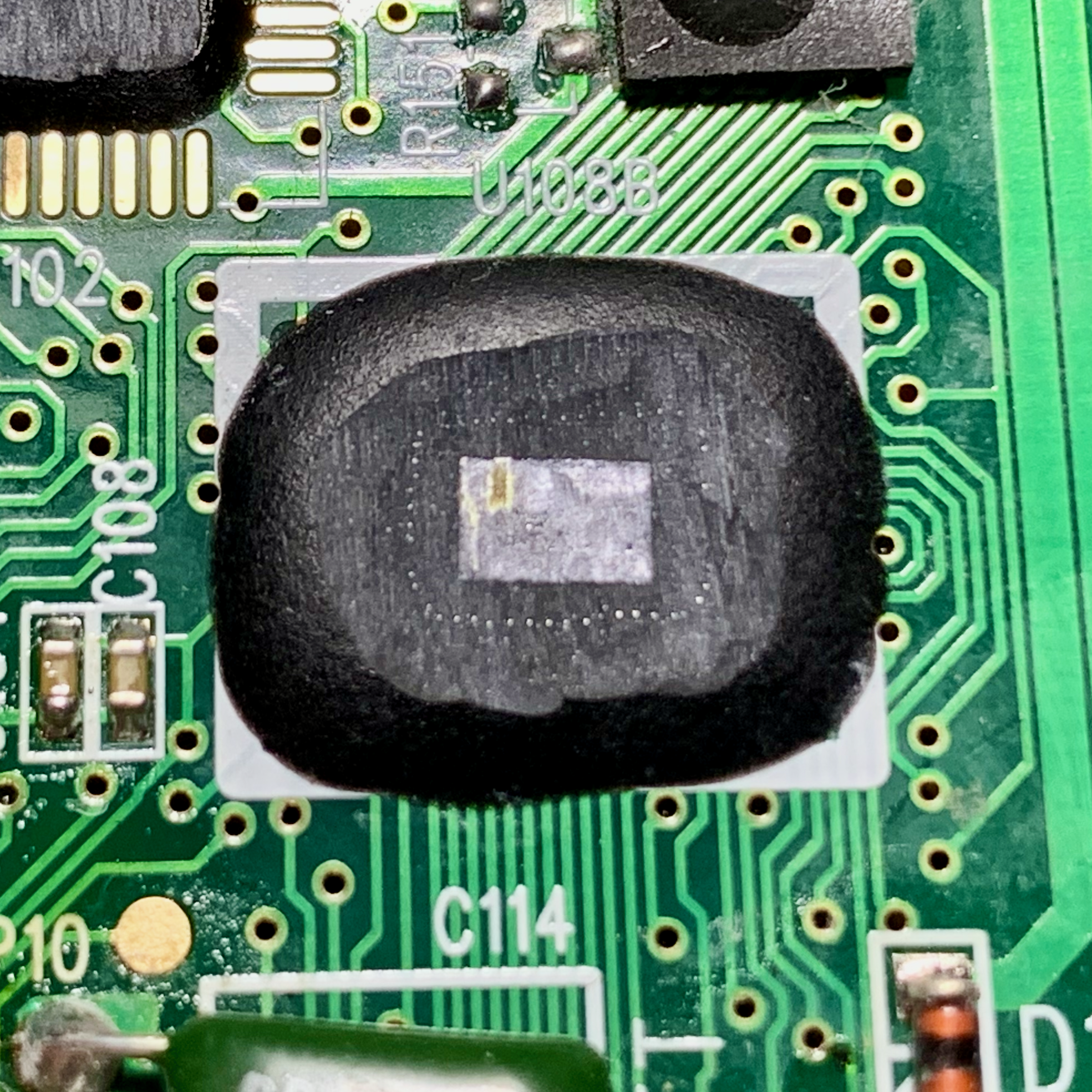
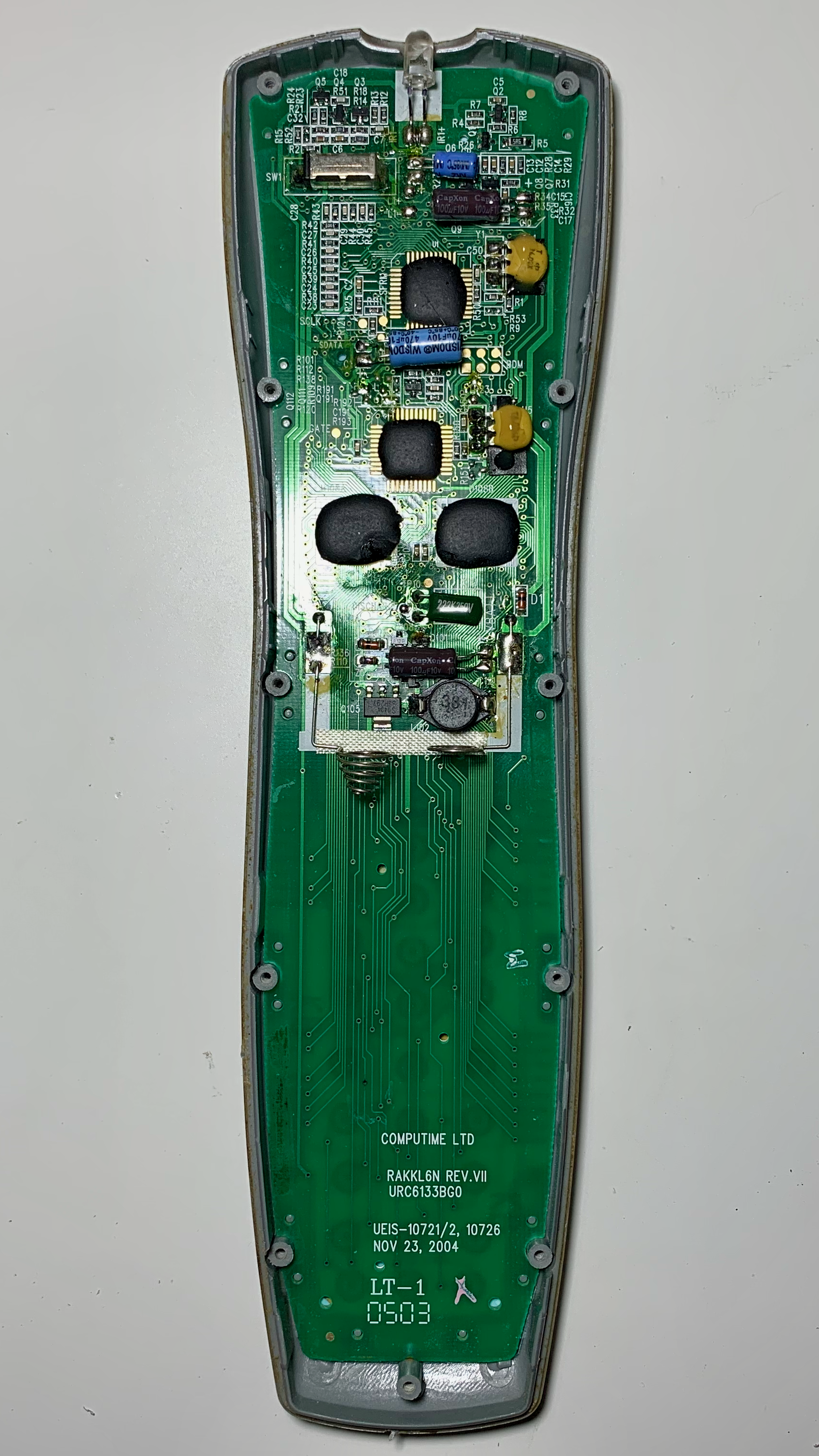
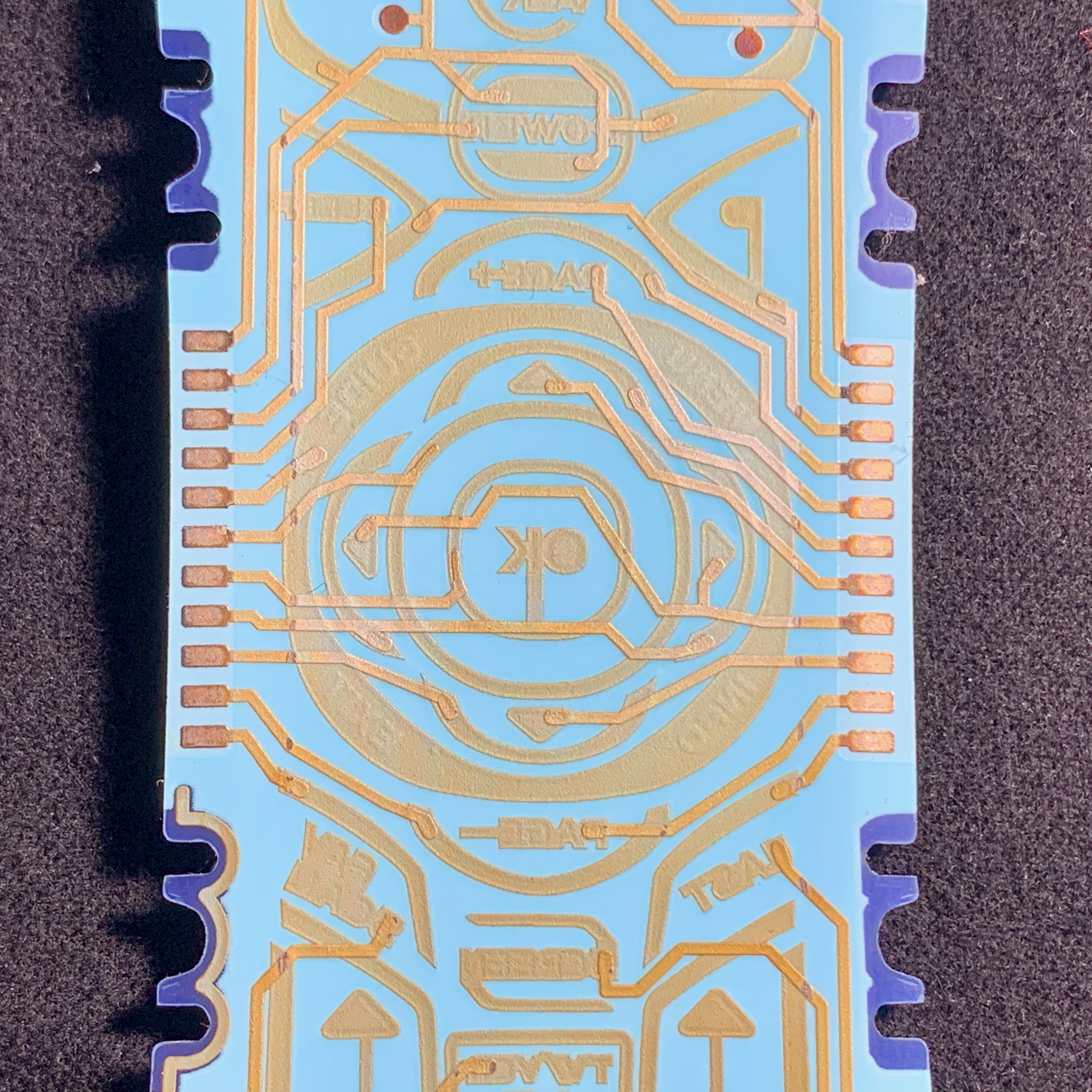
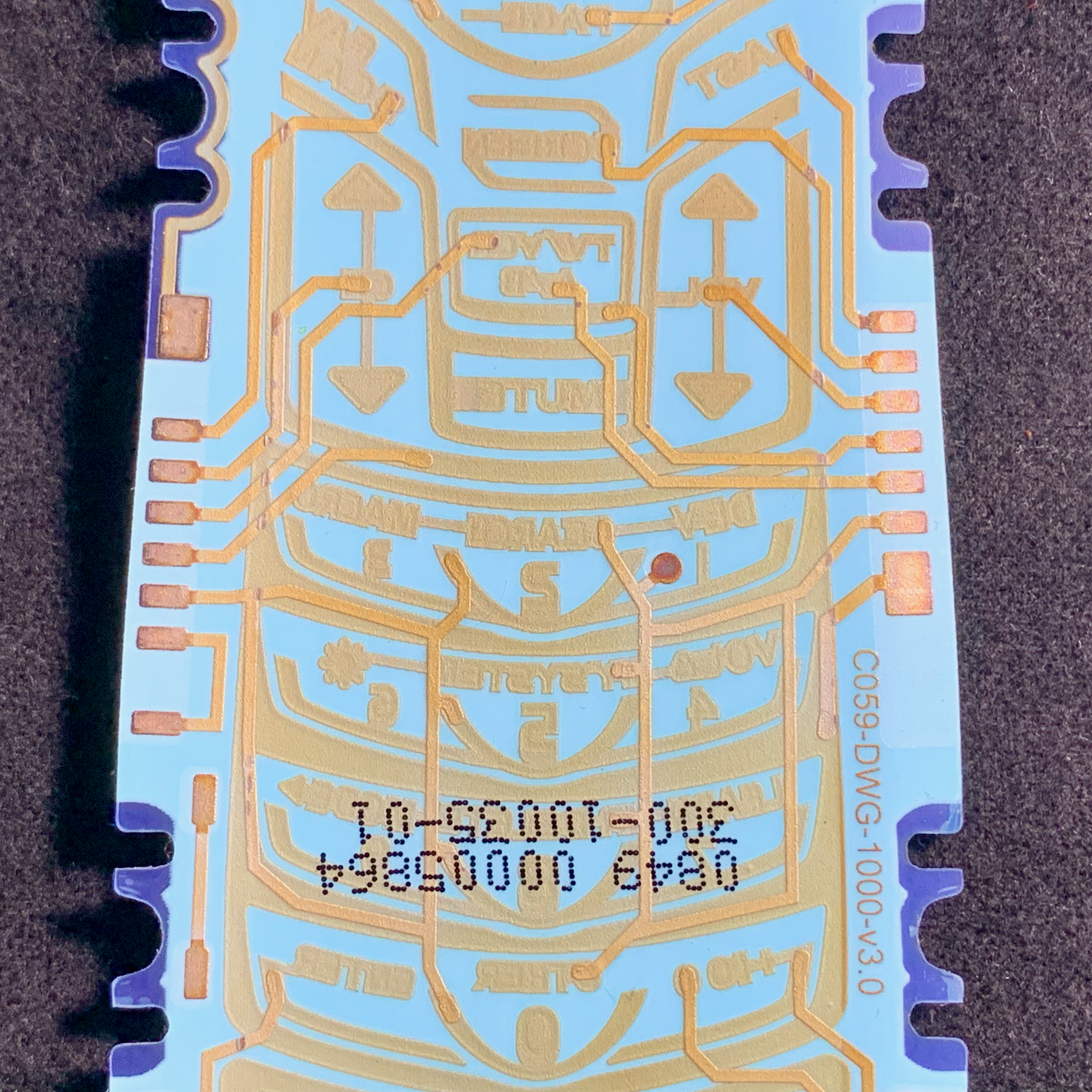
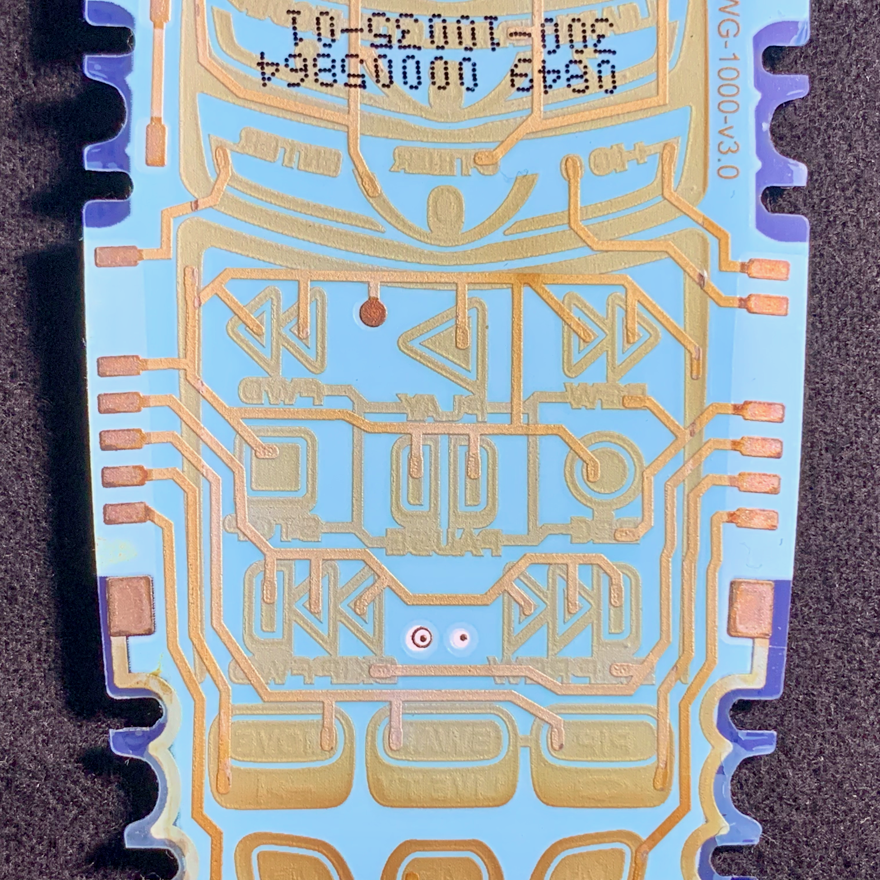
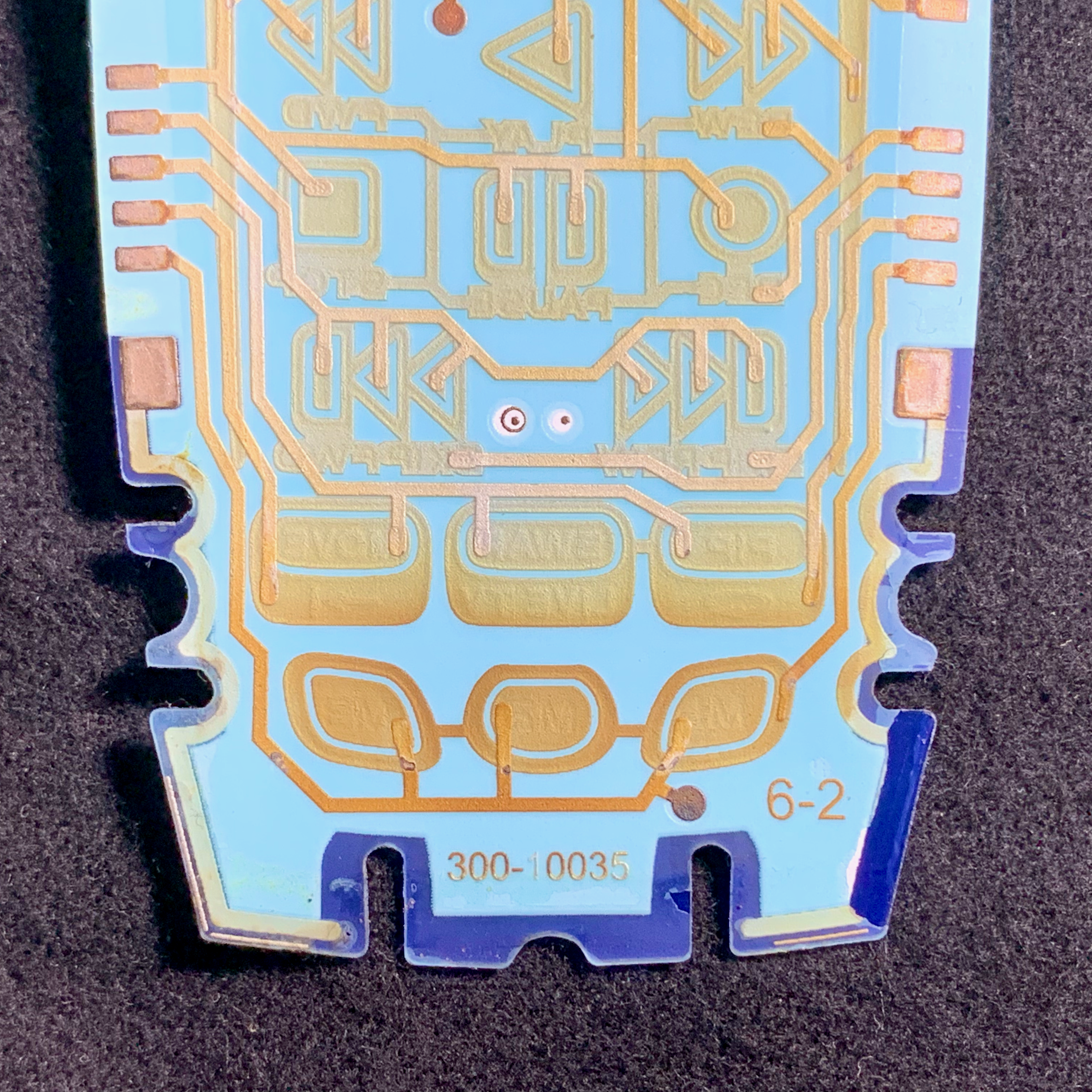
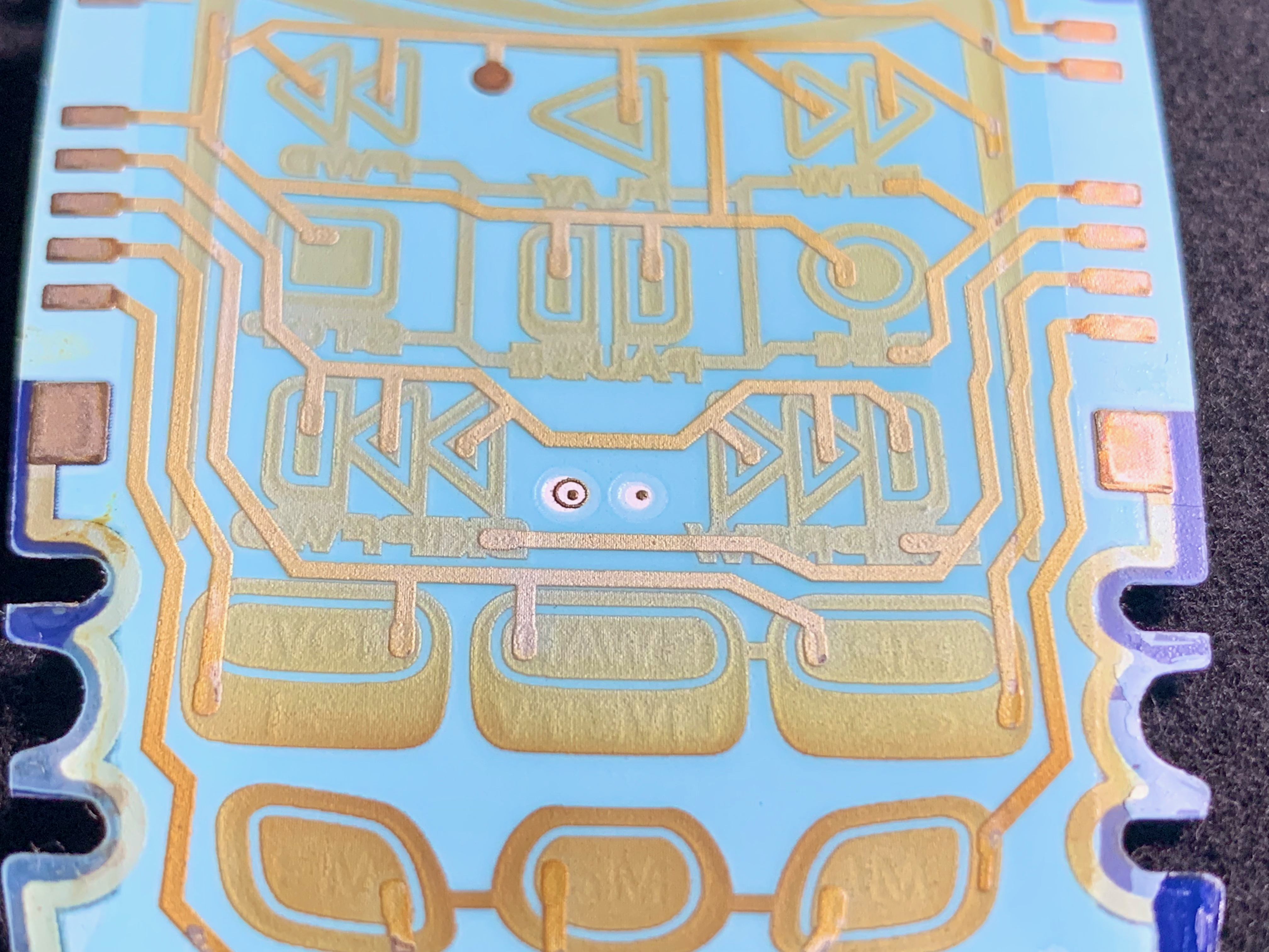
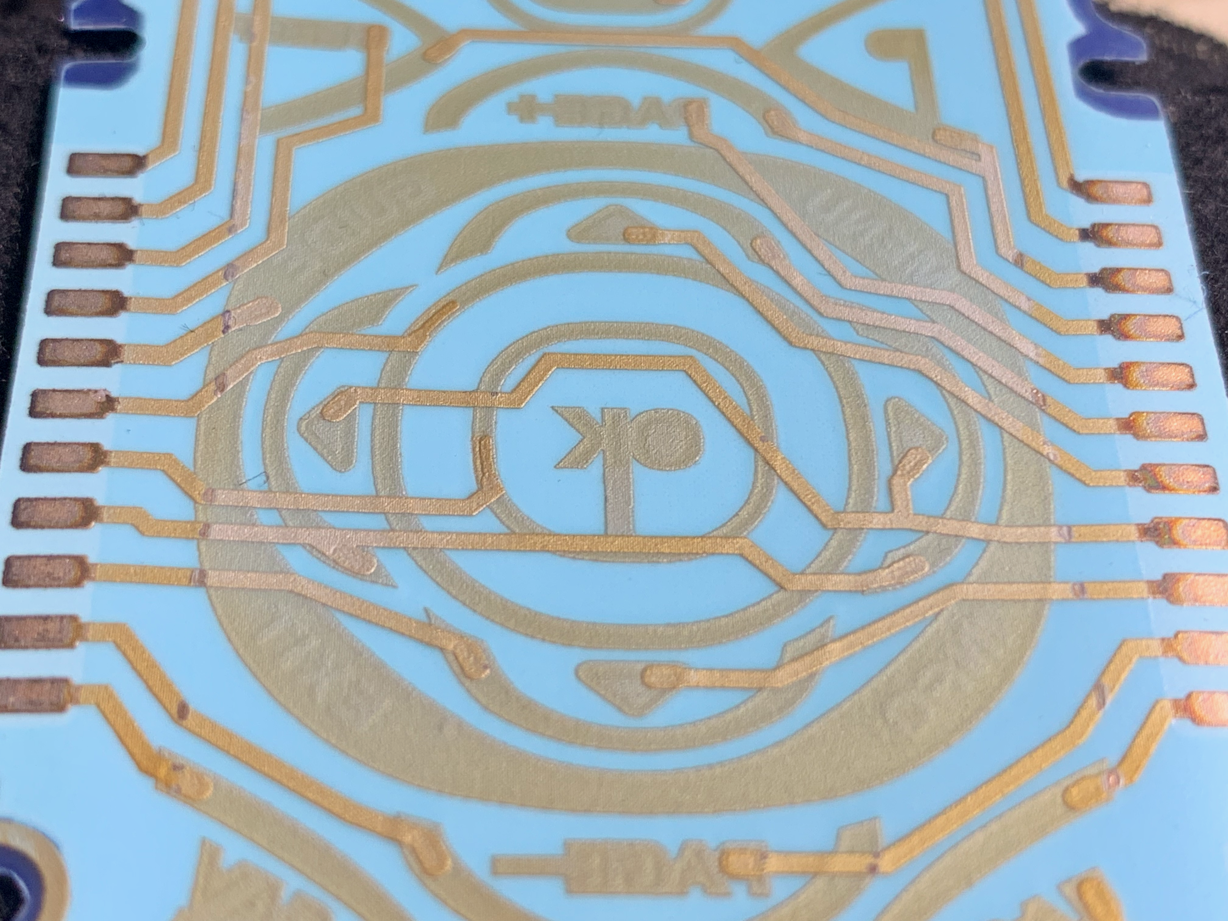
Circuit Board
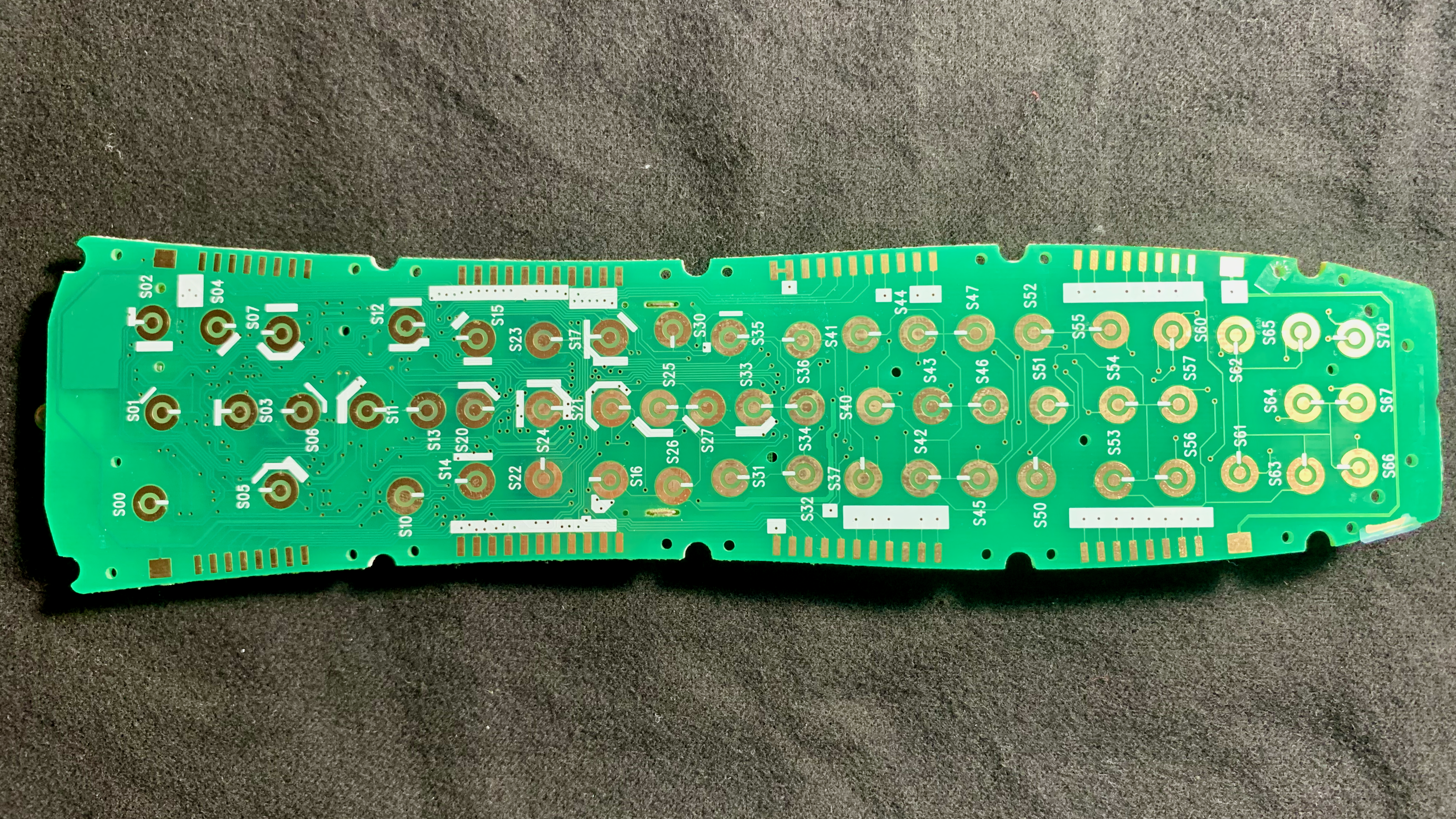
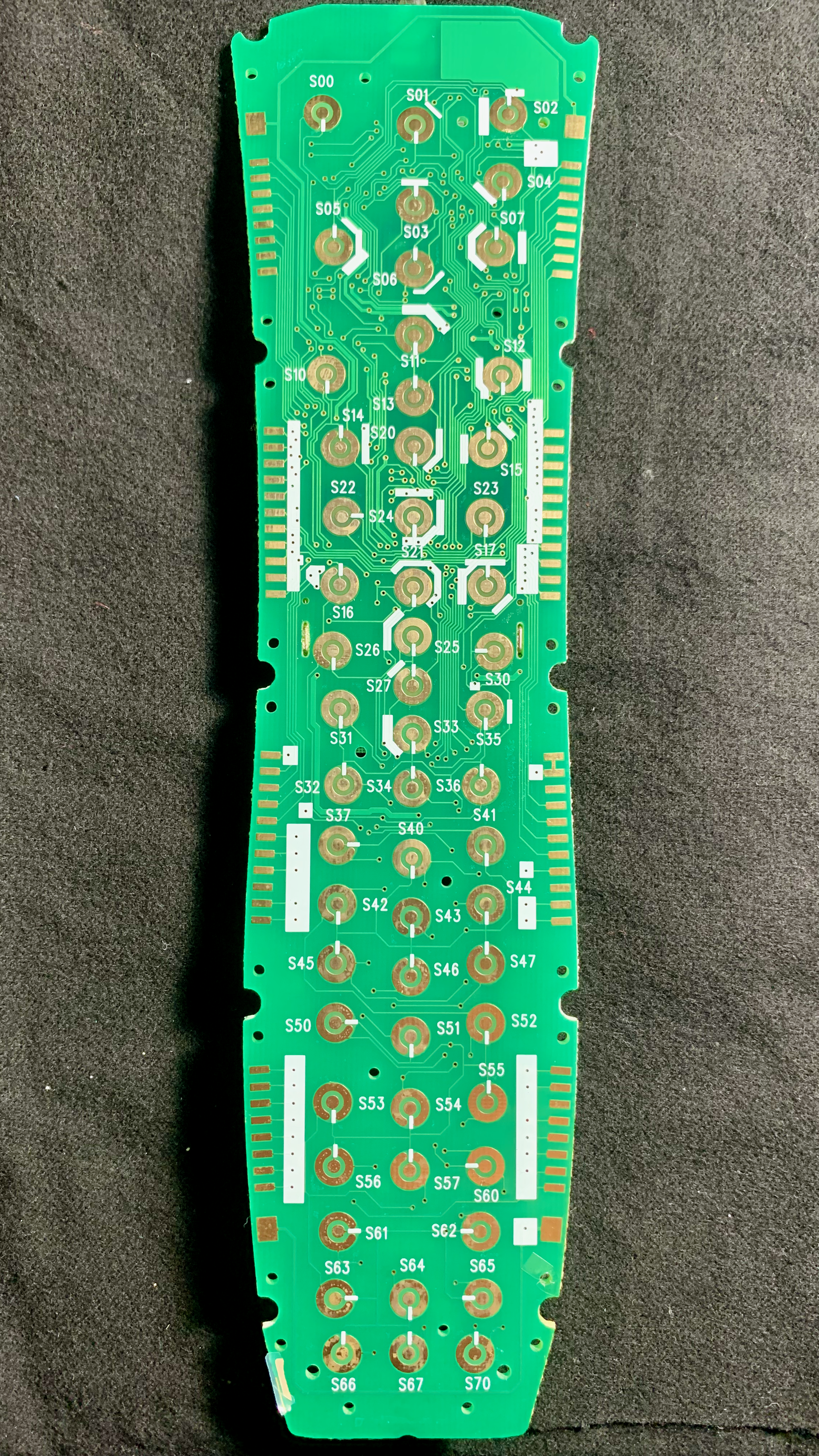
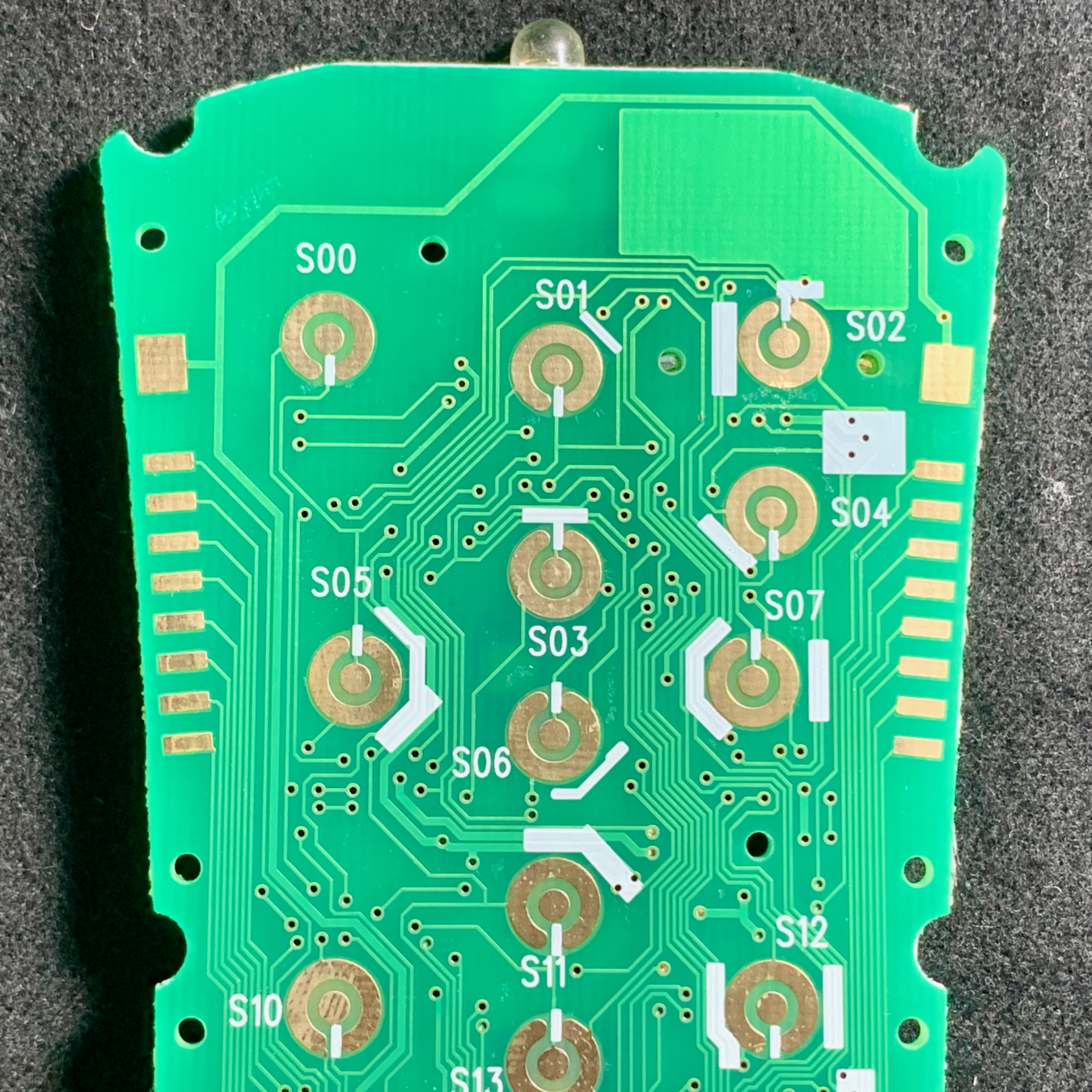
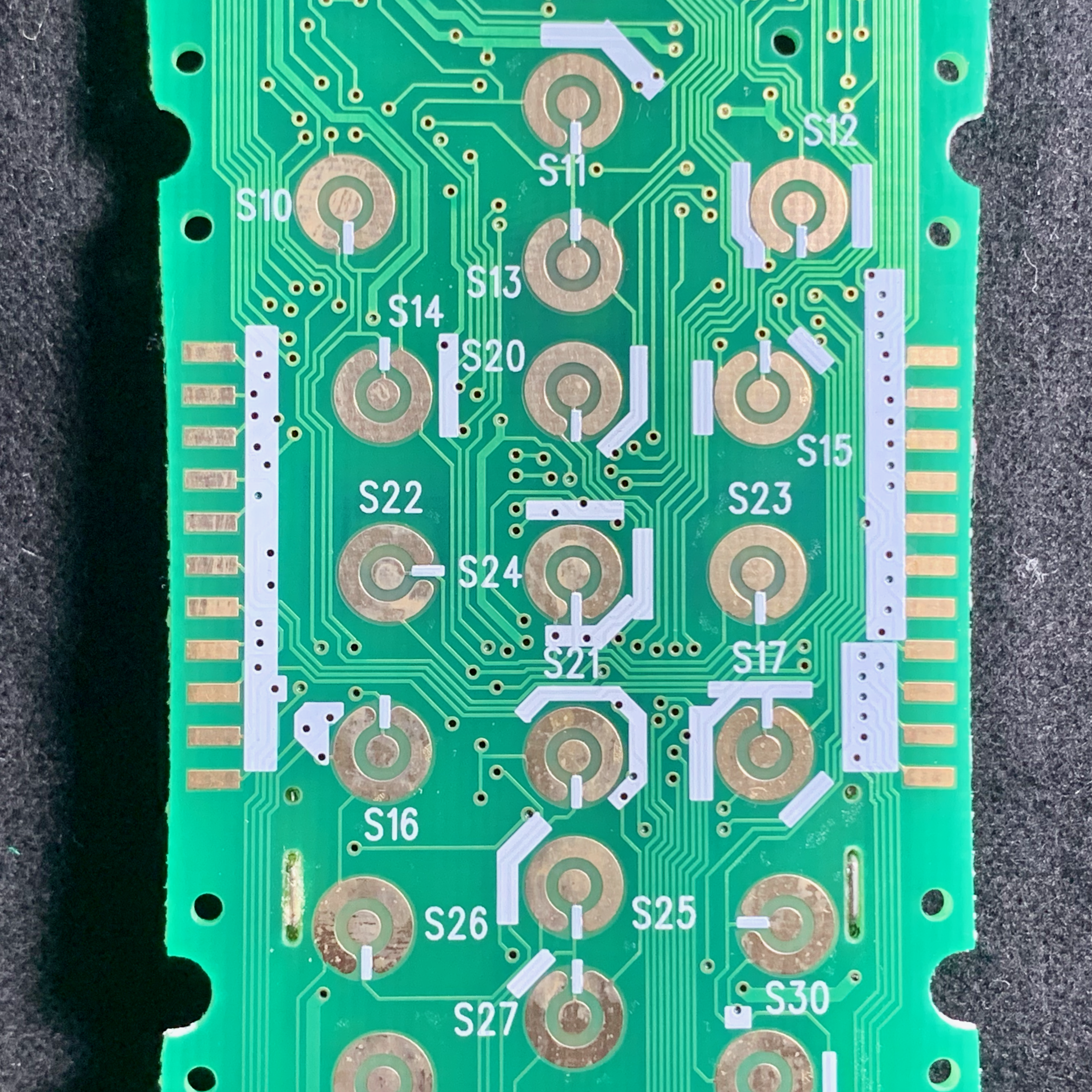
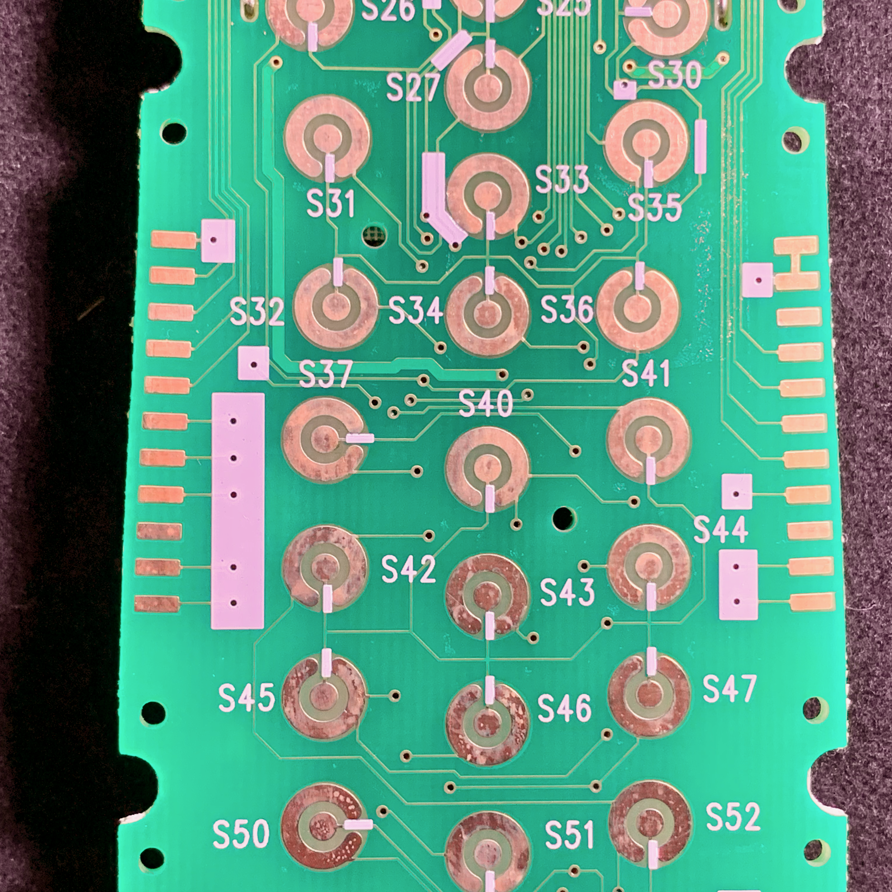
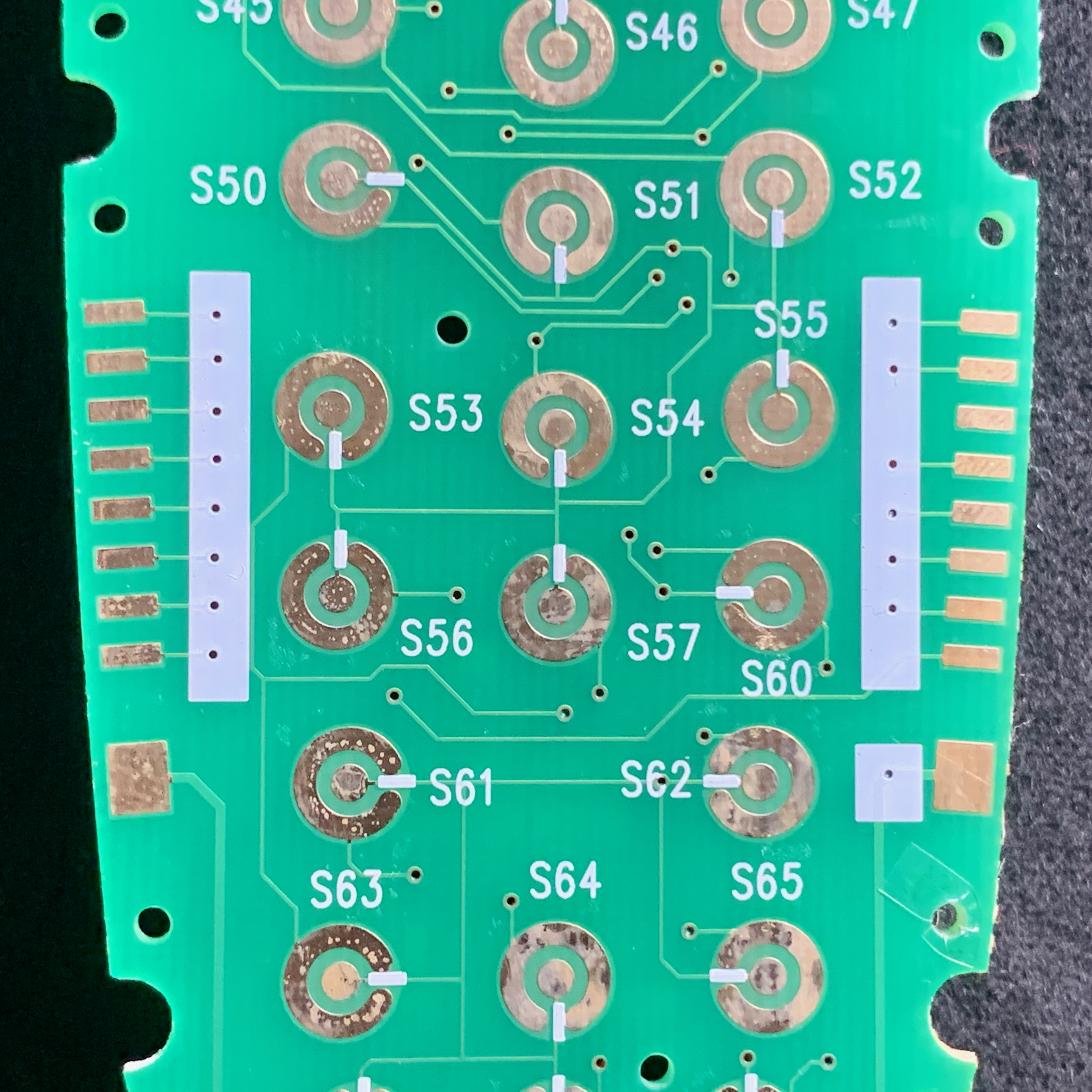
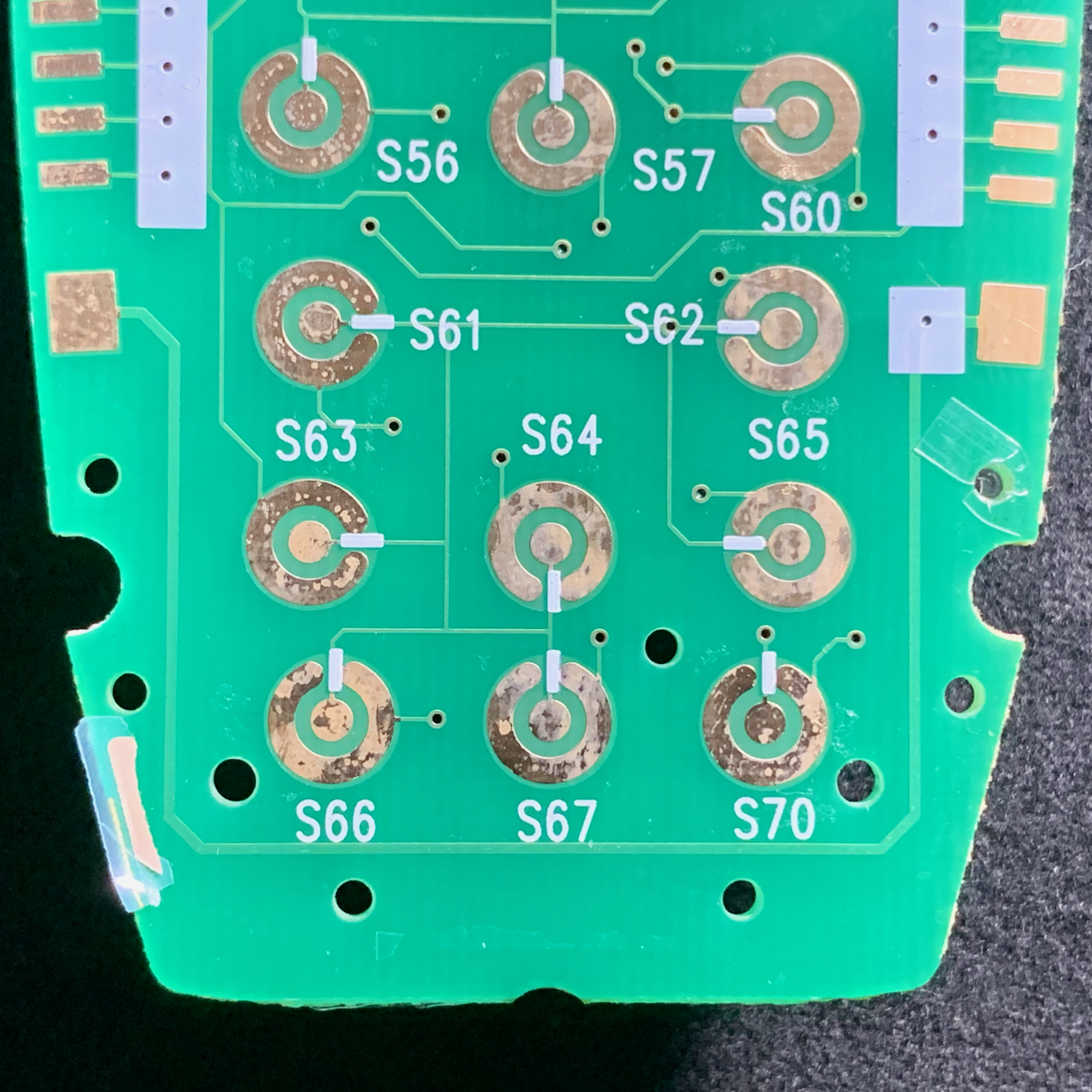
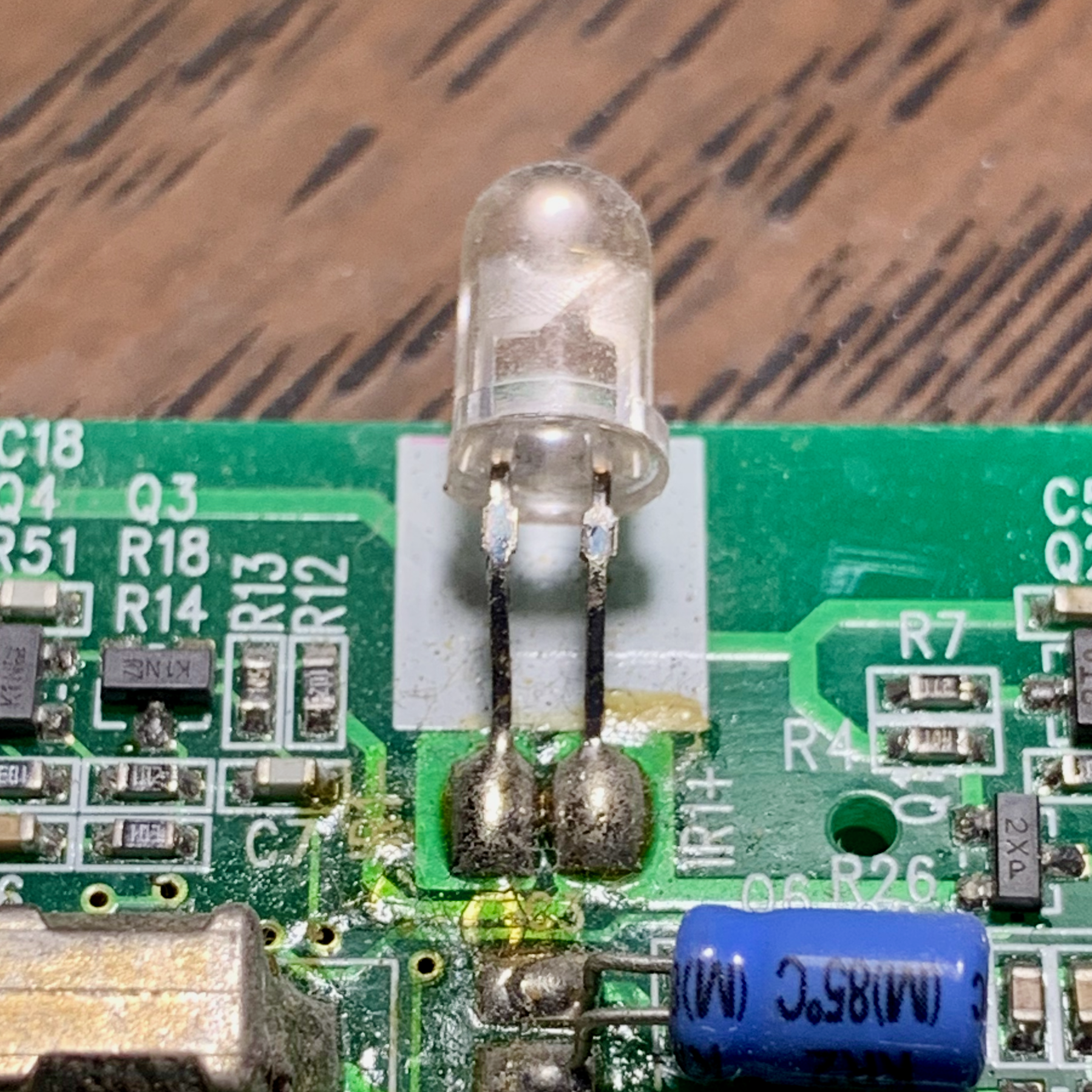
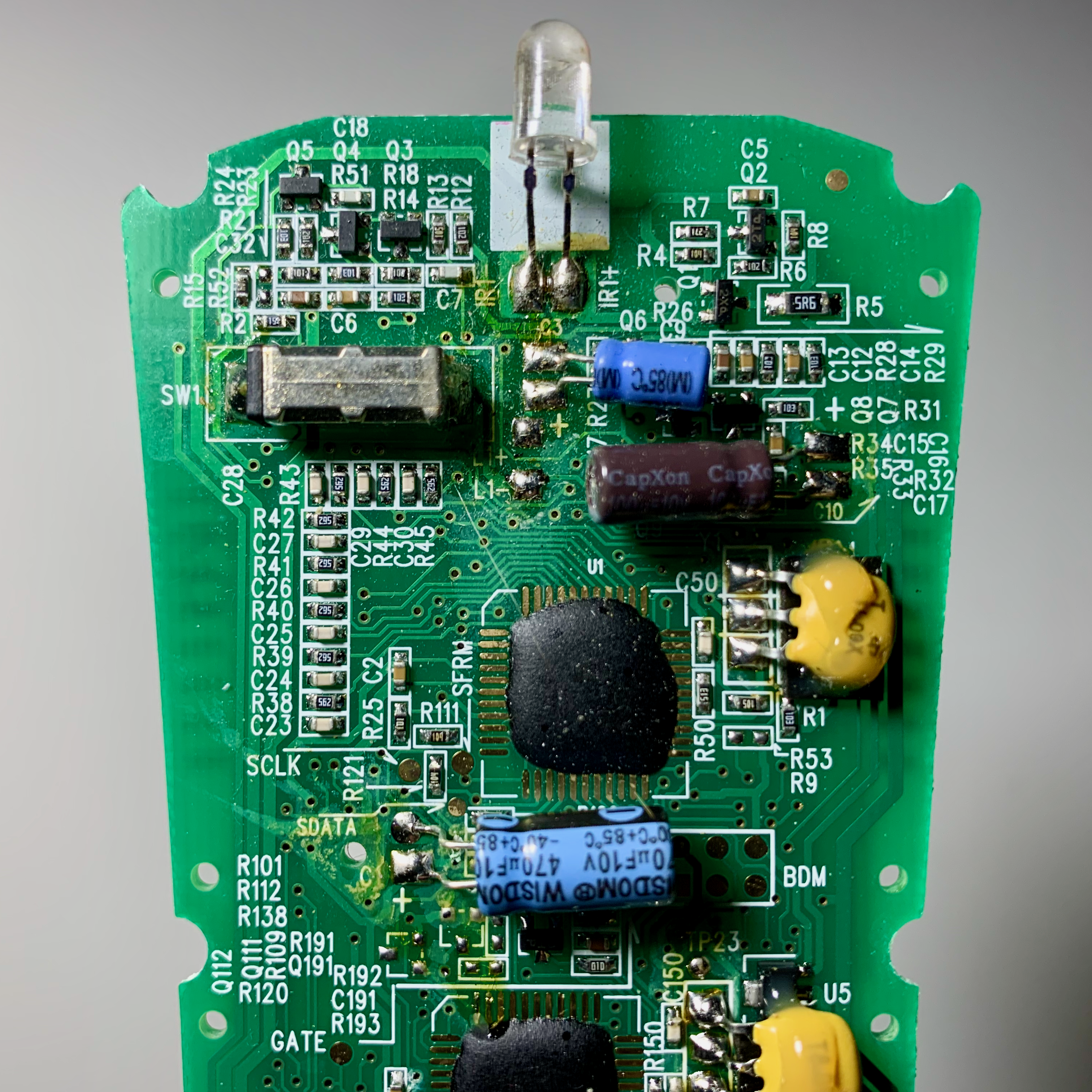
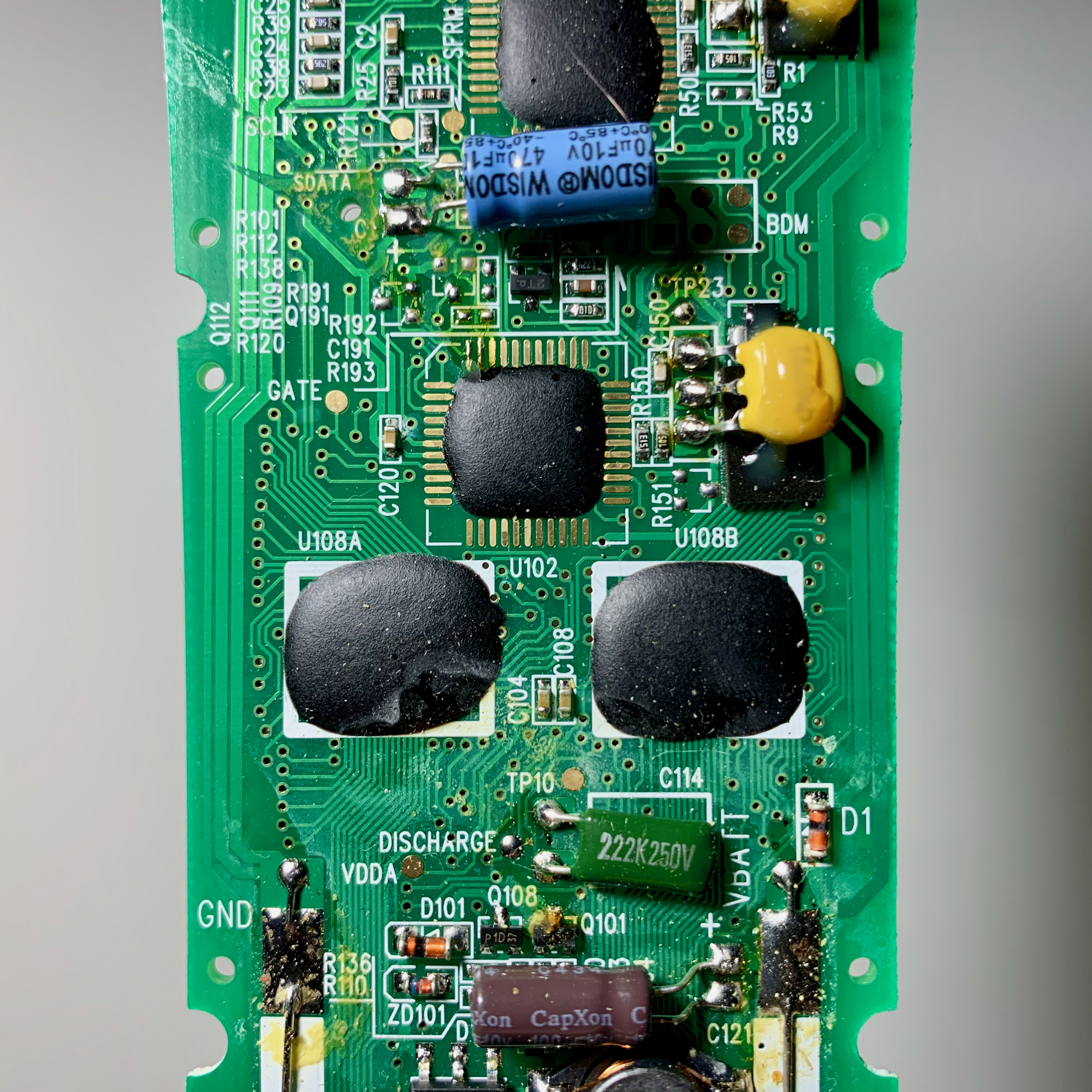
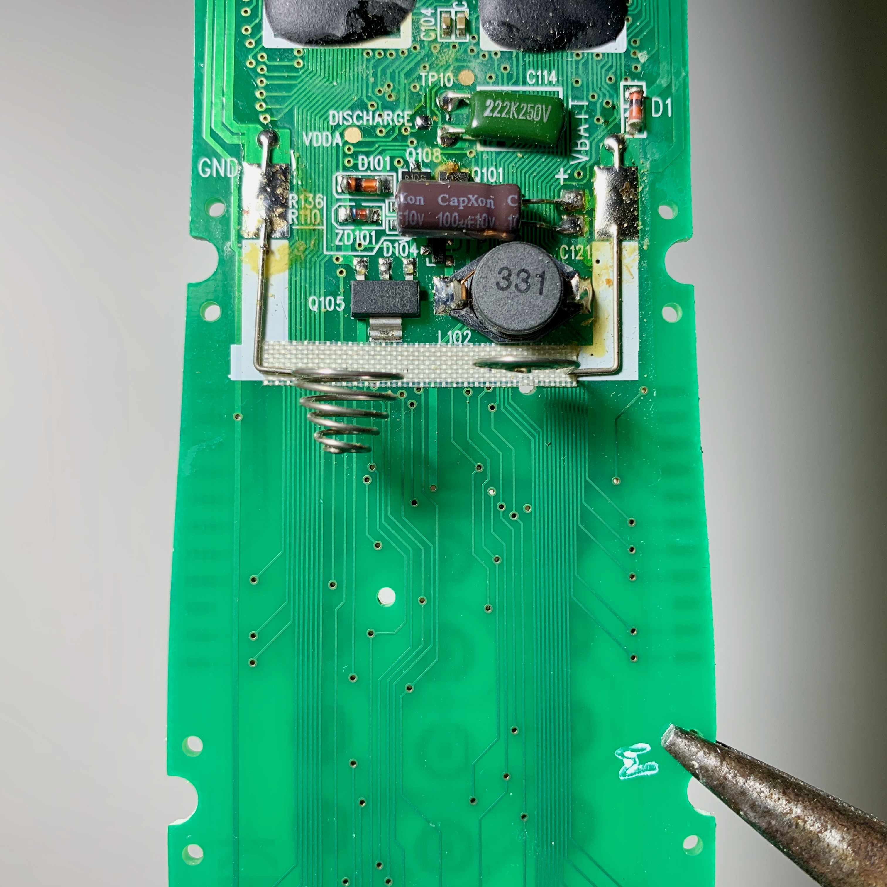
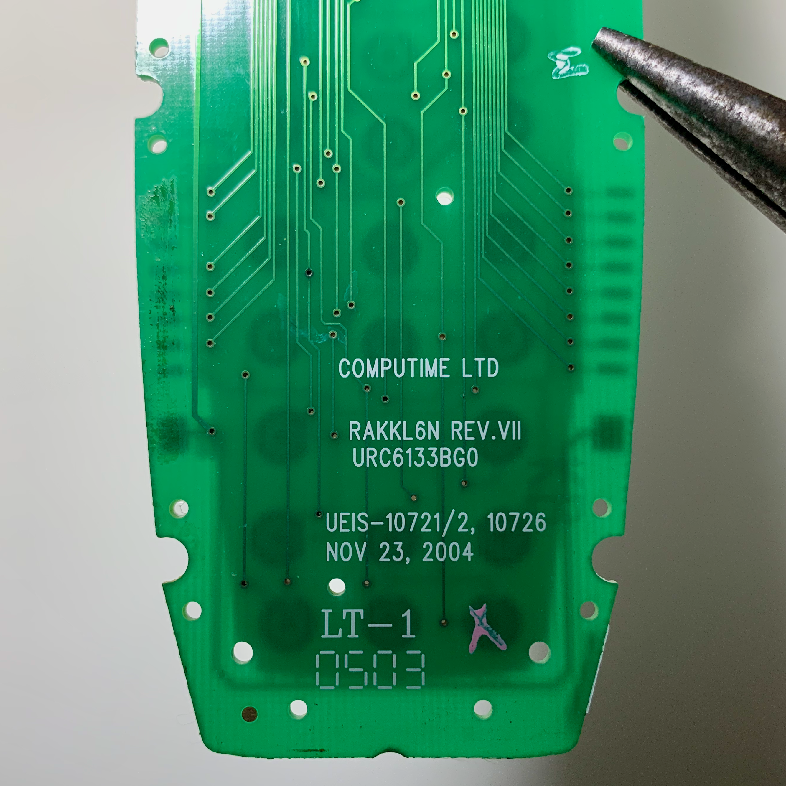
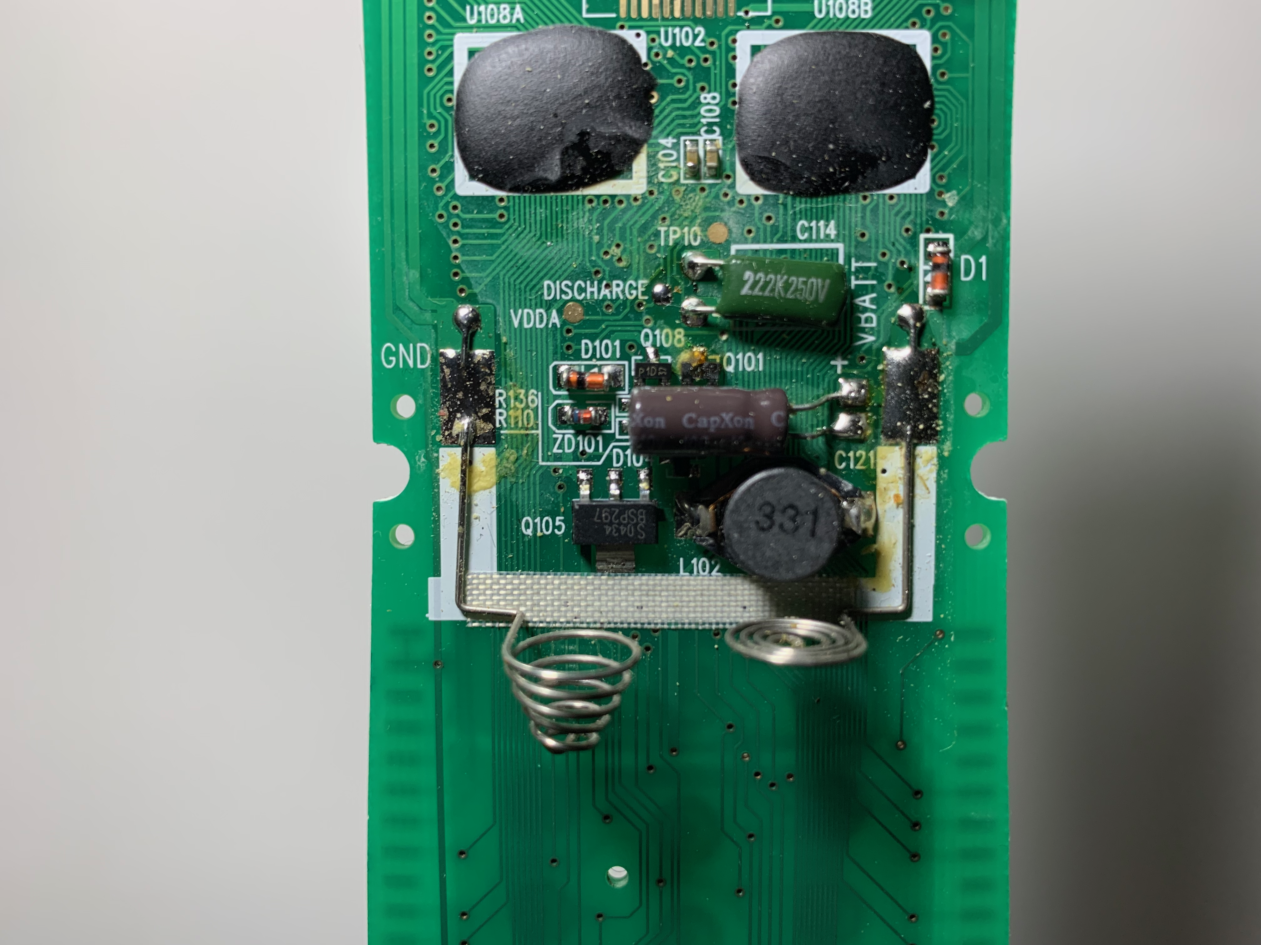
All of the ICs for the remote were covered by a black layer of epoxy potting material.
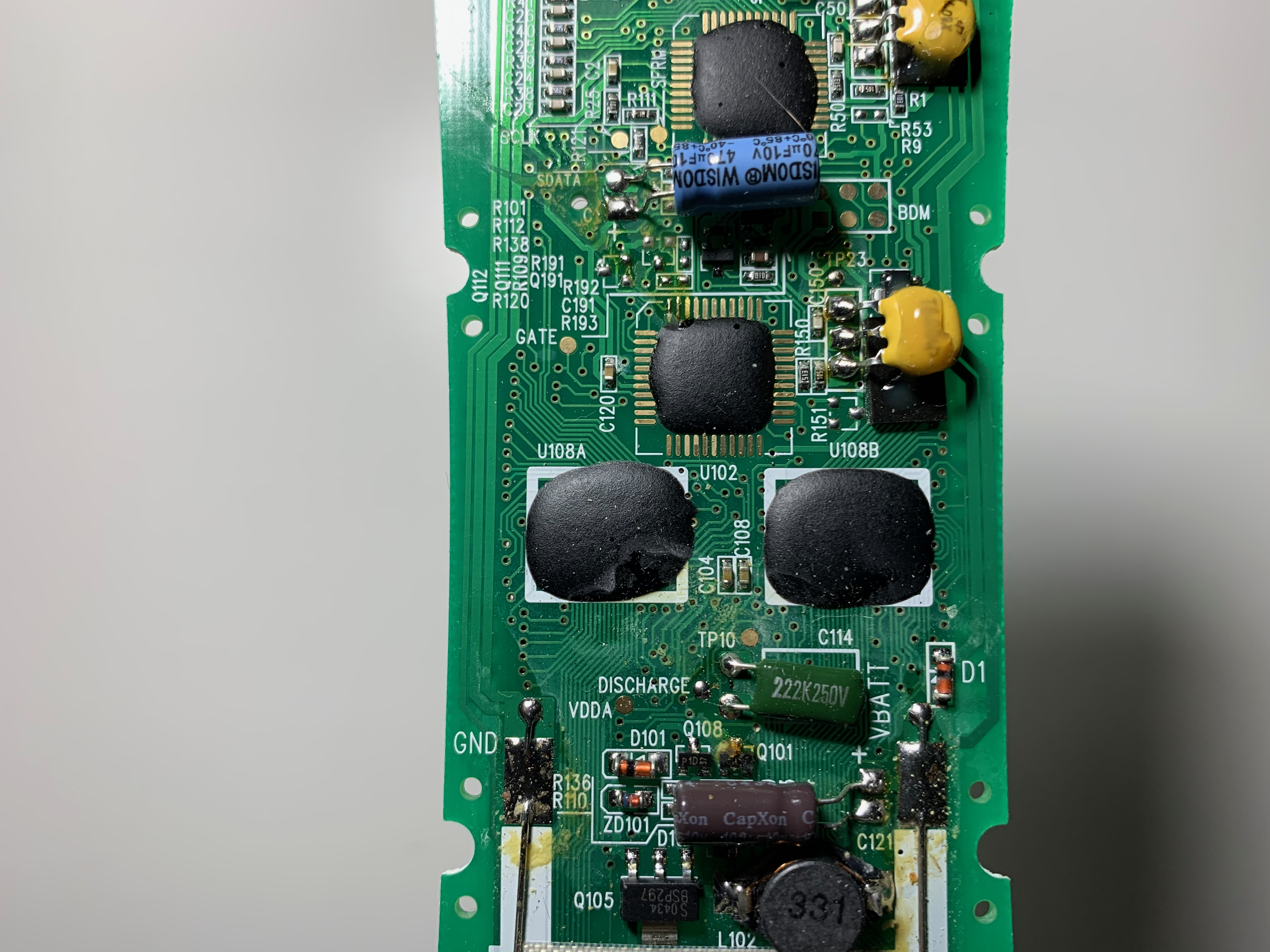
I used a Dremel with a small sanding drum to remove a portion of the epoxy. This had varying levels of success.