Over the years many of the lightbulbs in my house have been replaced with LED bulbs. I’ve always been curious what the inside of these looked like but didn’t want to destroy a good bulb. Luckily, I’ve recently had a couple of LED bulbs stop working.
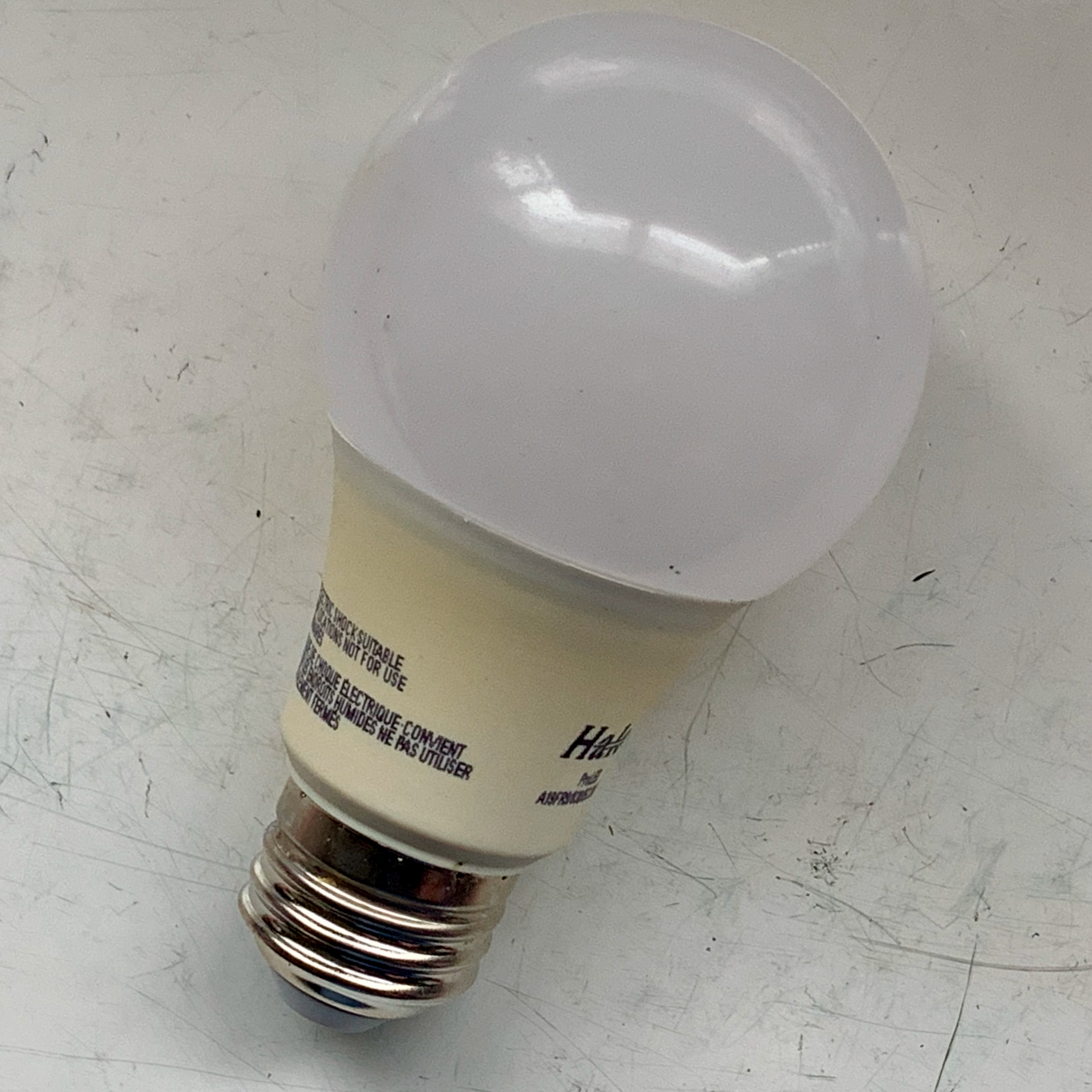
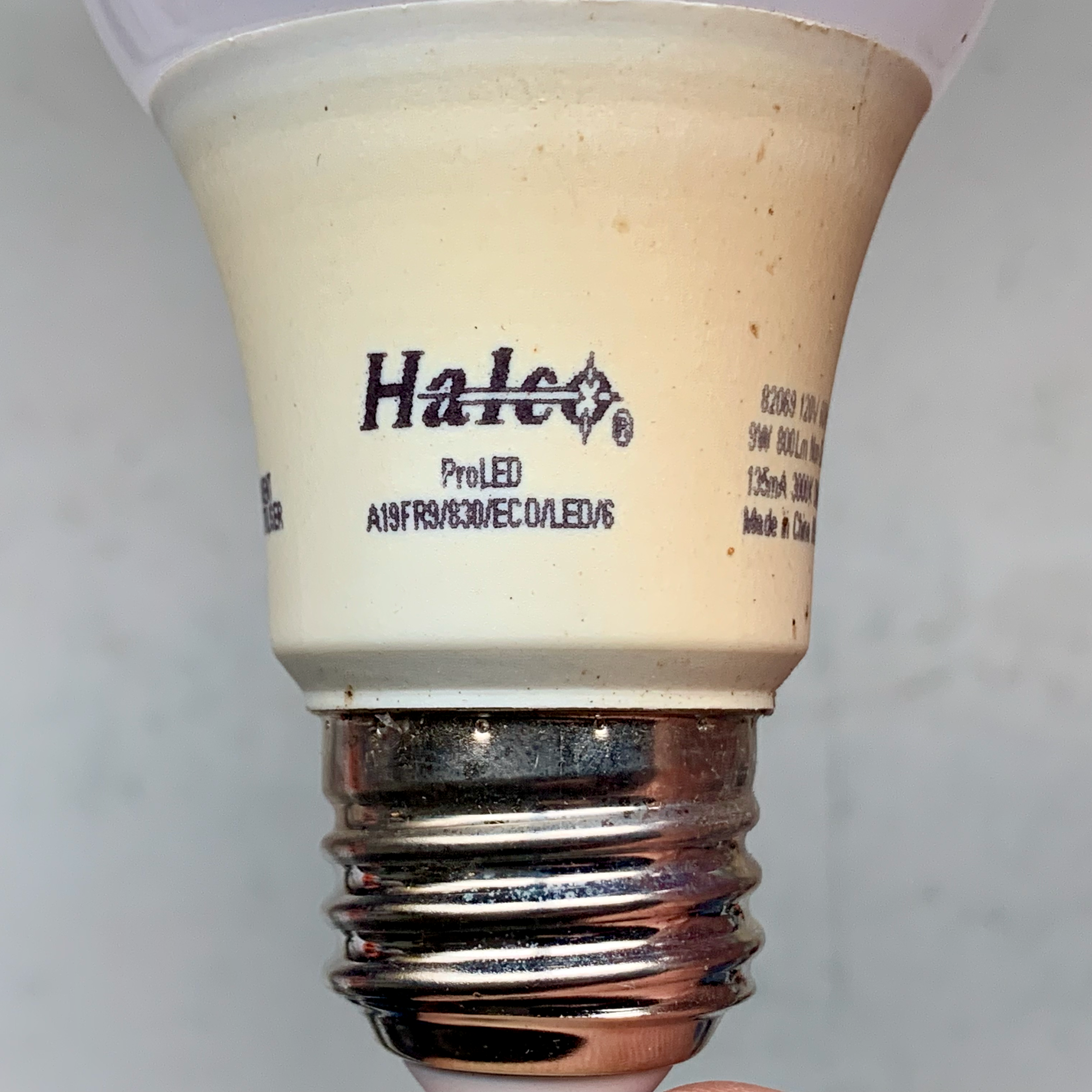
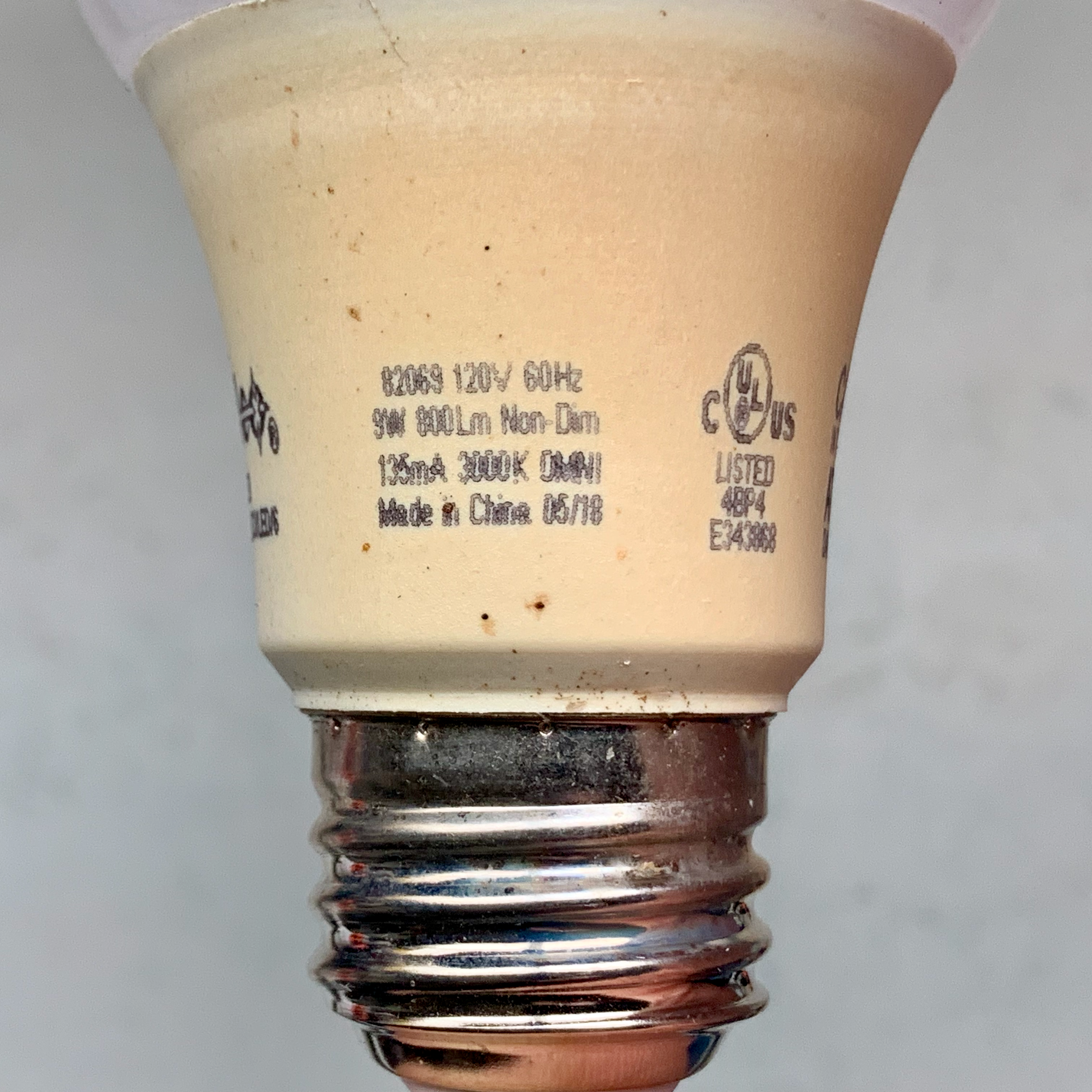
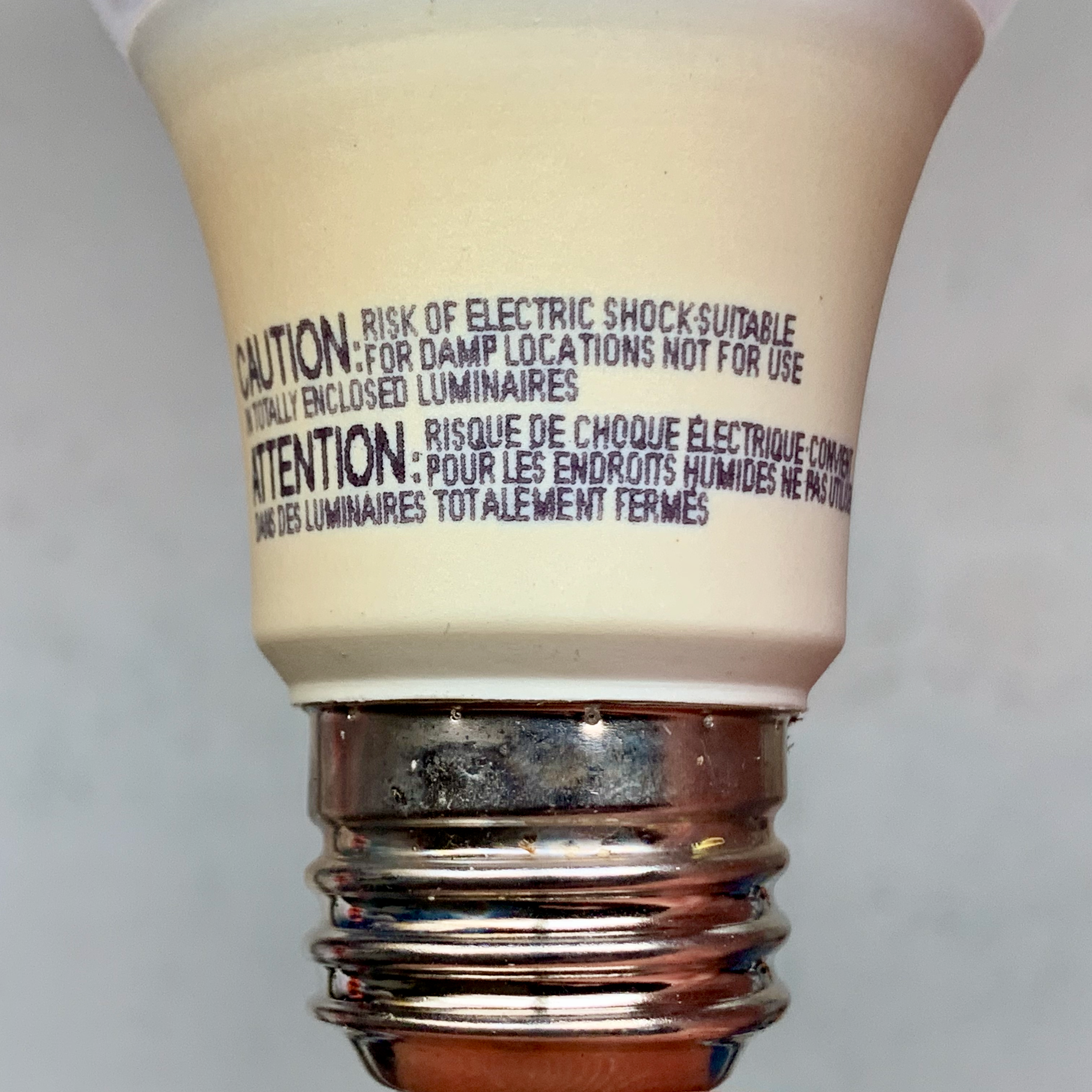
The bulb we’re going to look at today is a ProLED A19FR9 Bulb from Halo.
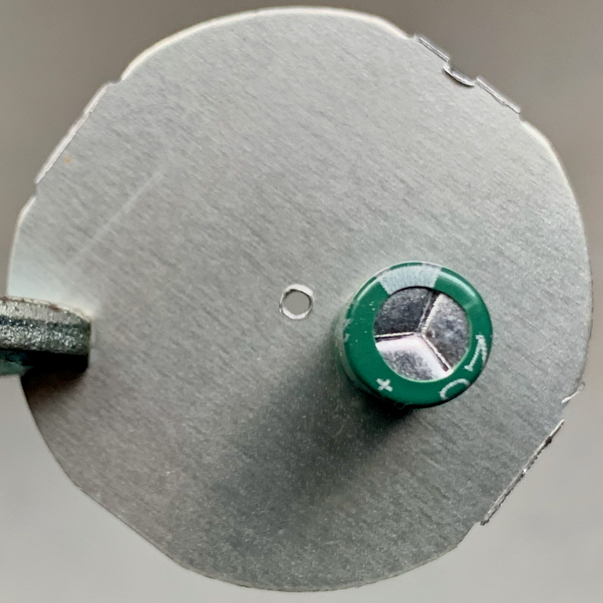
Removing the platic dome from the bulb was relatively easy. The dome was only held in place by a thin layer of adhesive around the lip.
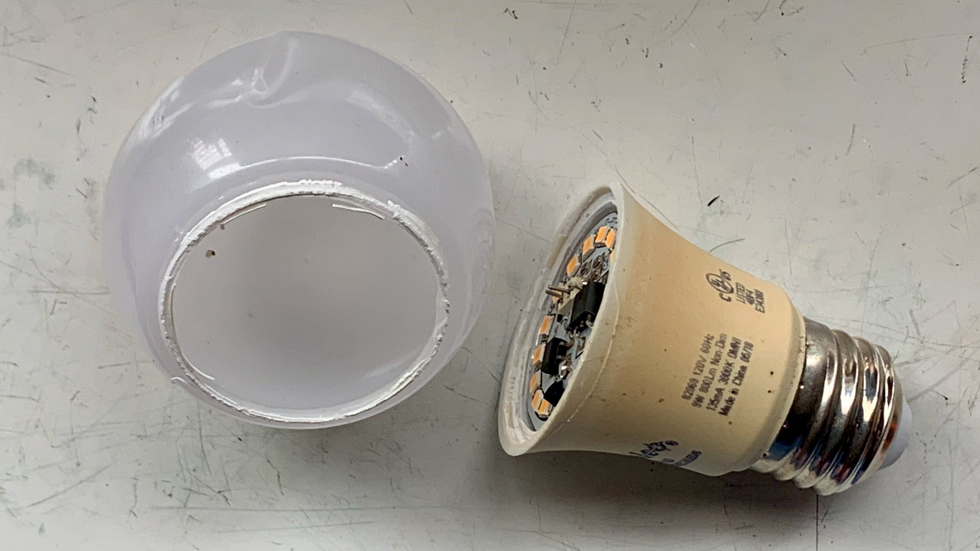
Removing the dome exposed the small metalic circuit board housing nearly all of the bulb components.
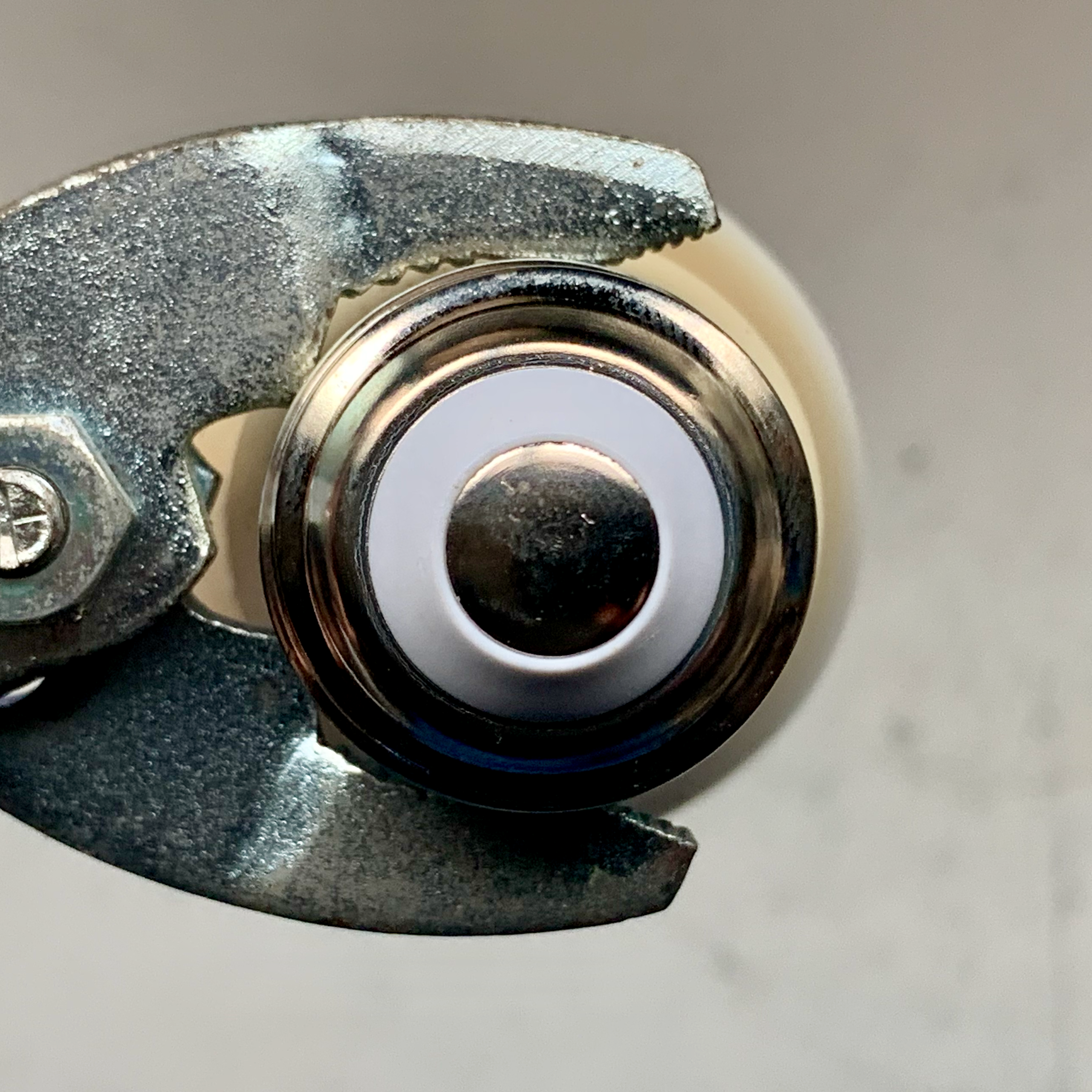
The only component not on the circuit board was a large resistor suspended inline with the lead connecting the power input to the circuit board.
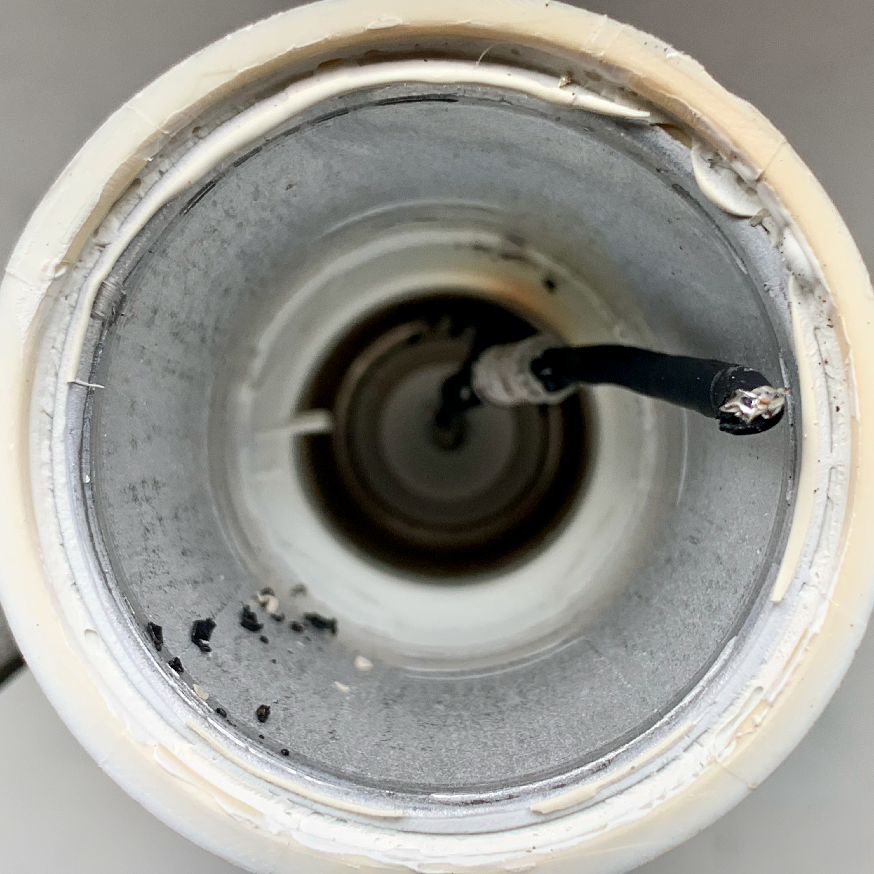
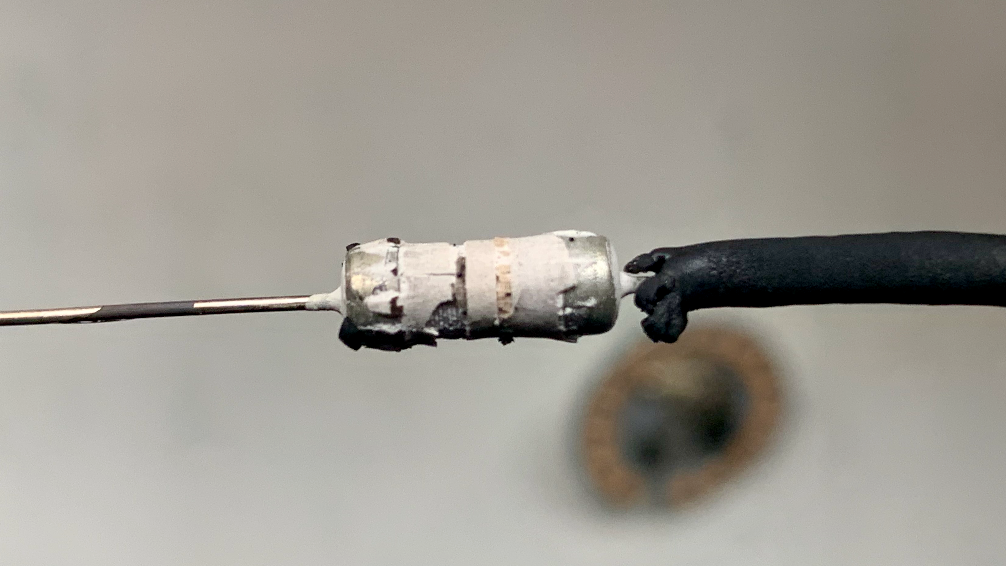
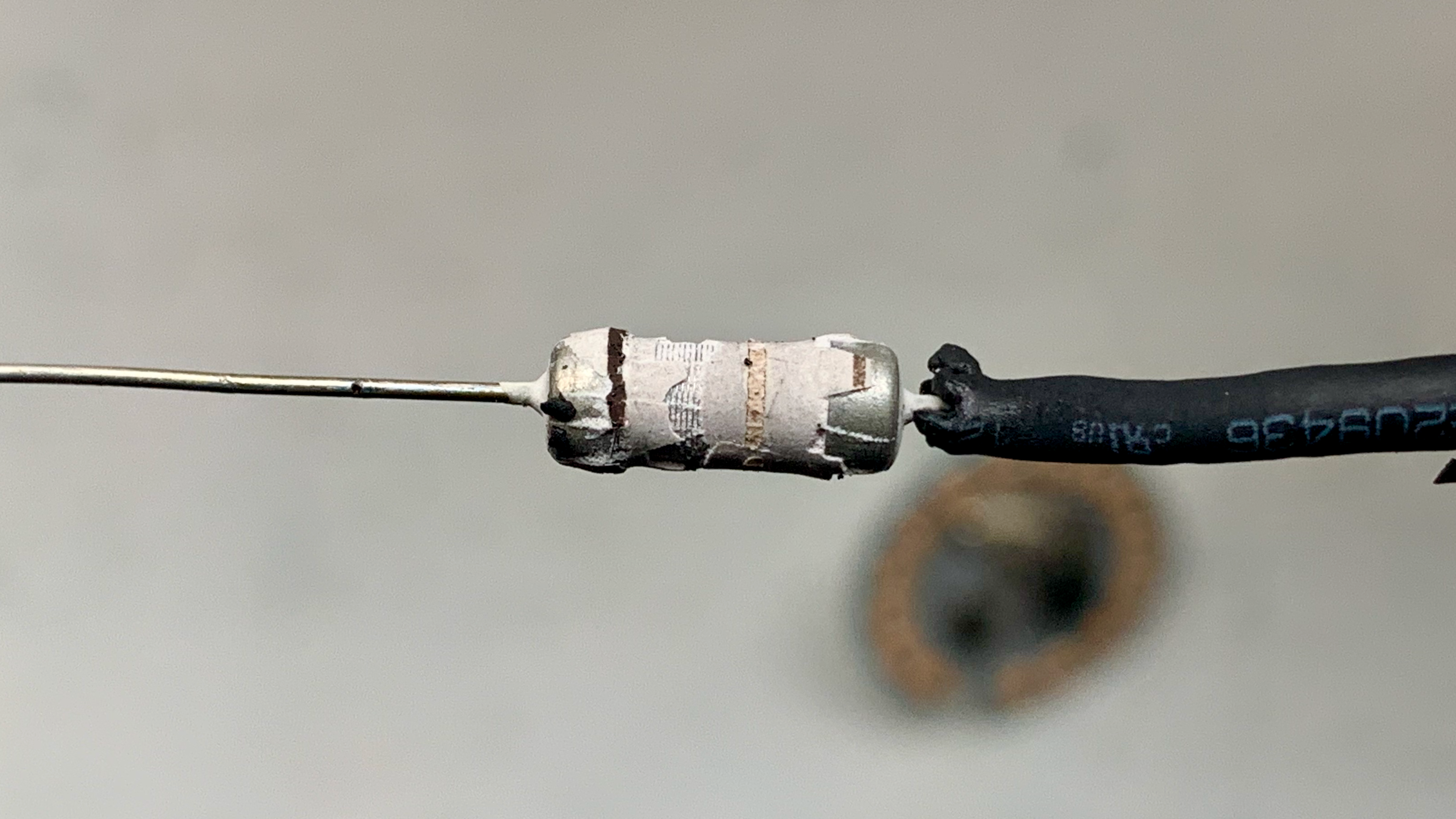
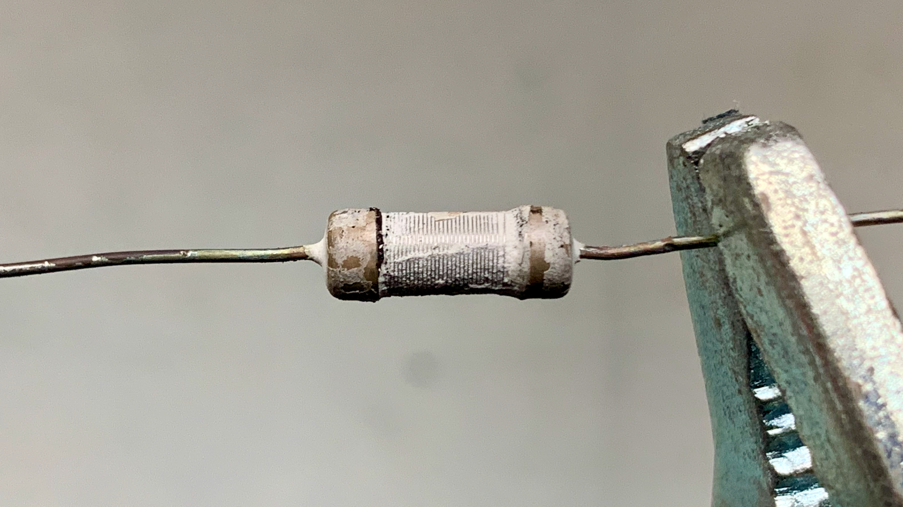
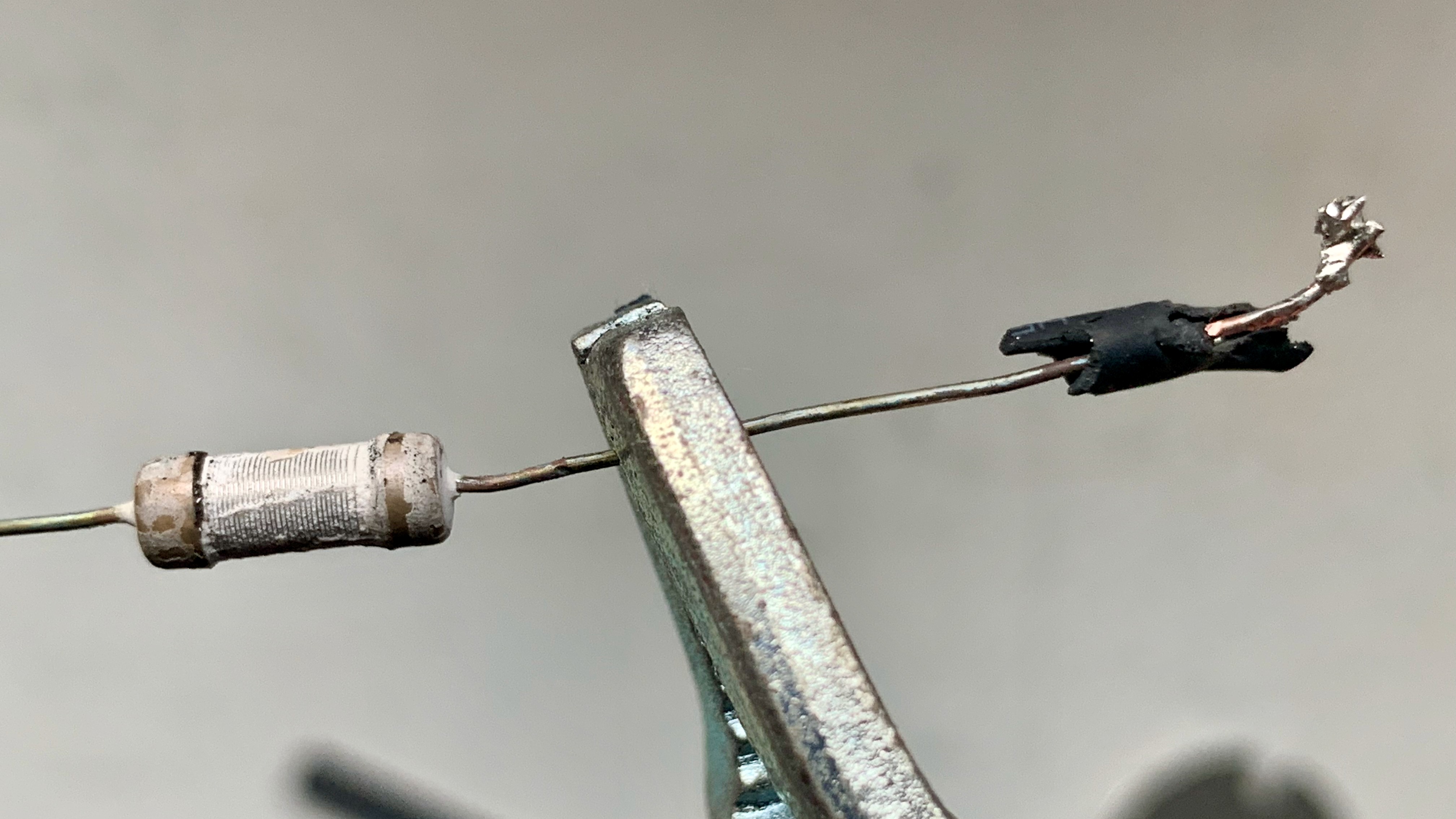
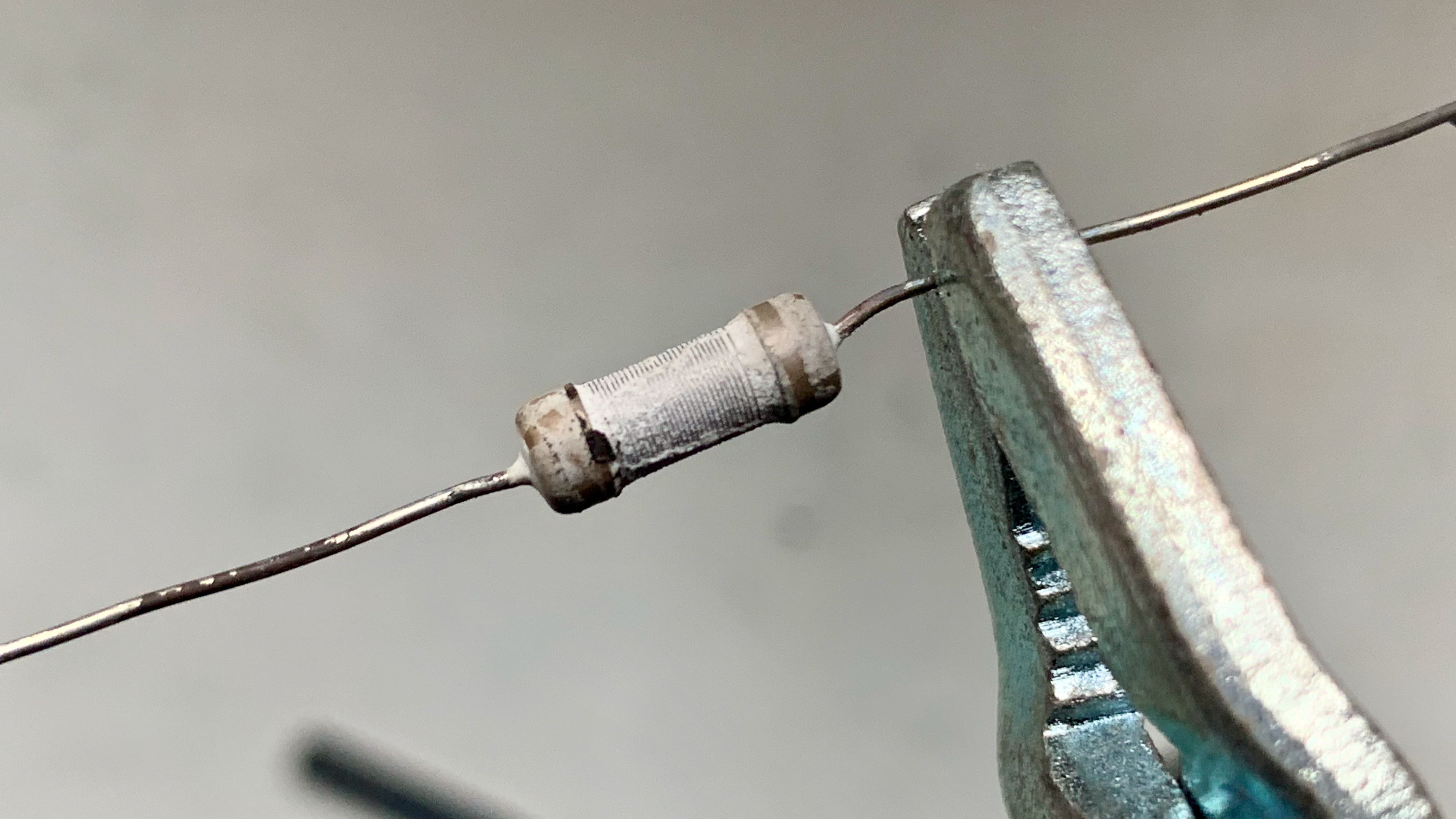
The visual appearance of this component clearly indicates that it is the point of failure.
Circuit Board
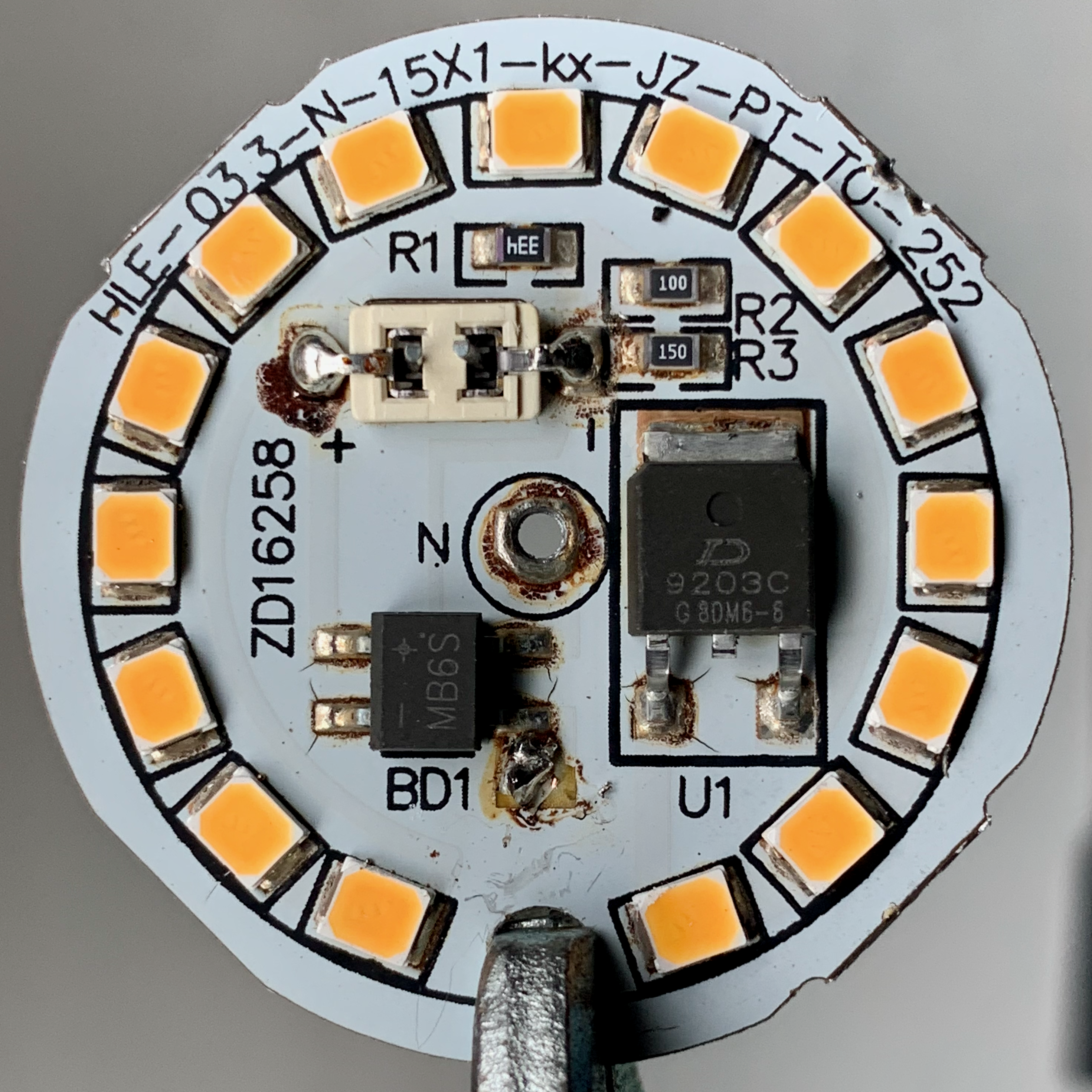
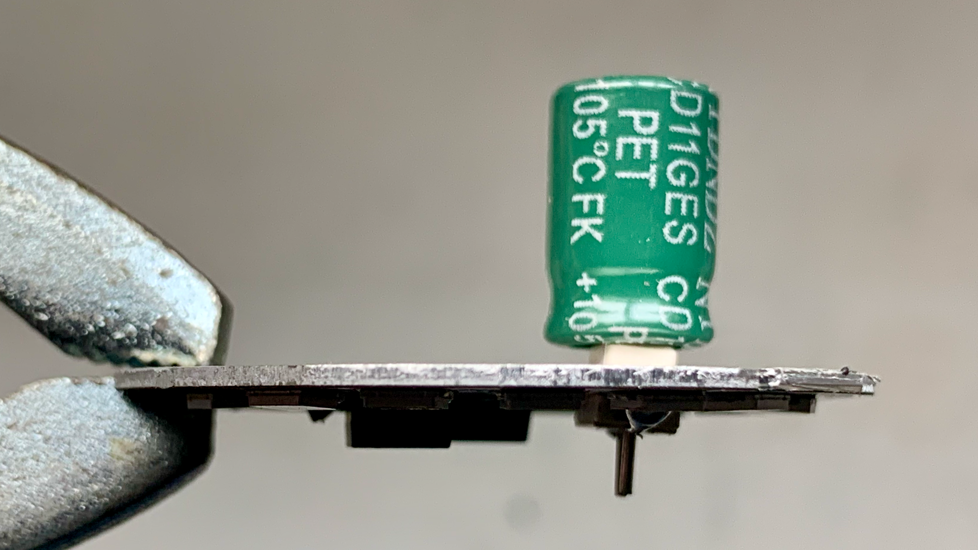
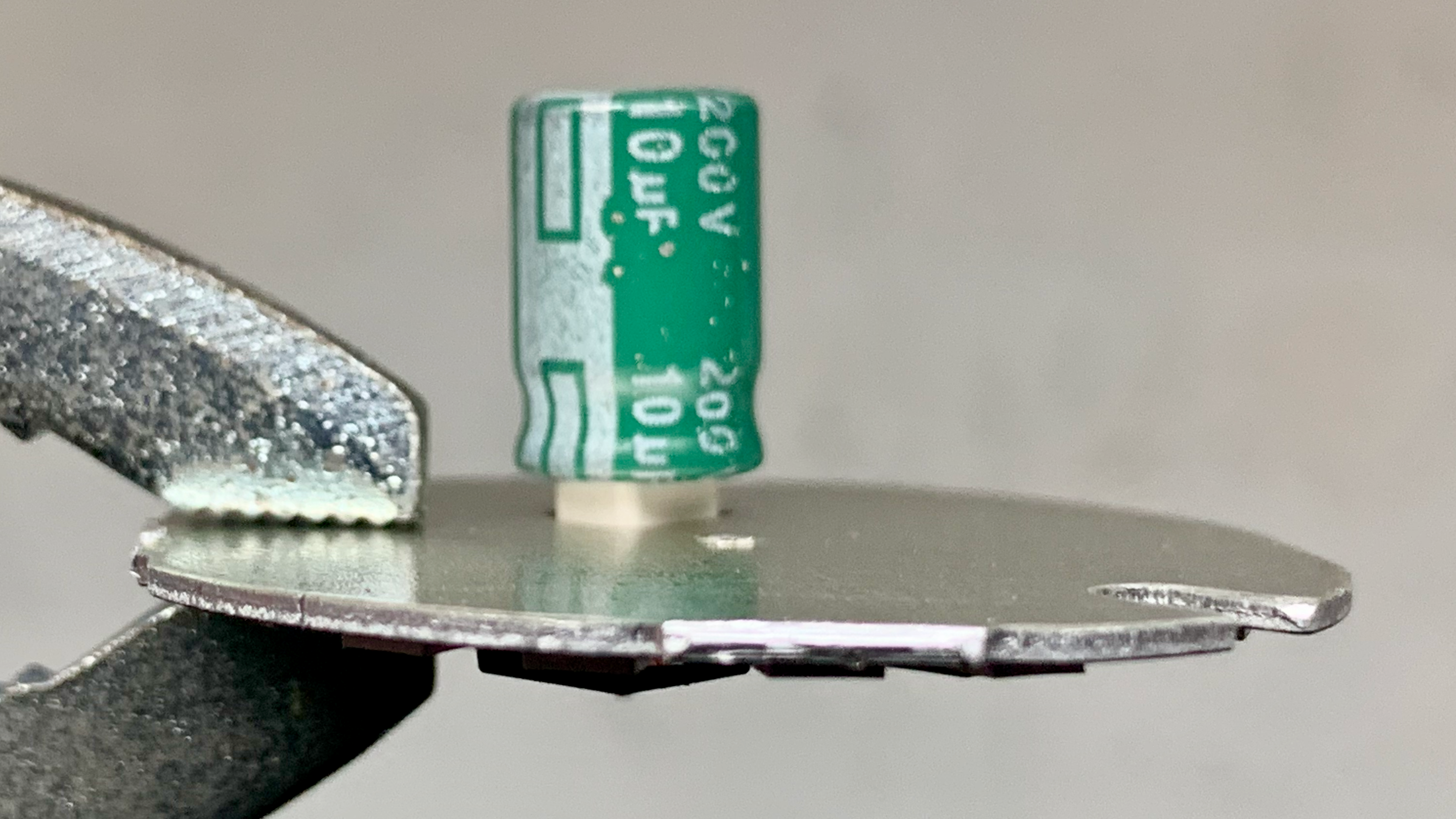
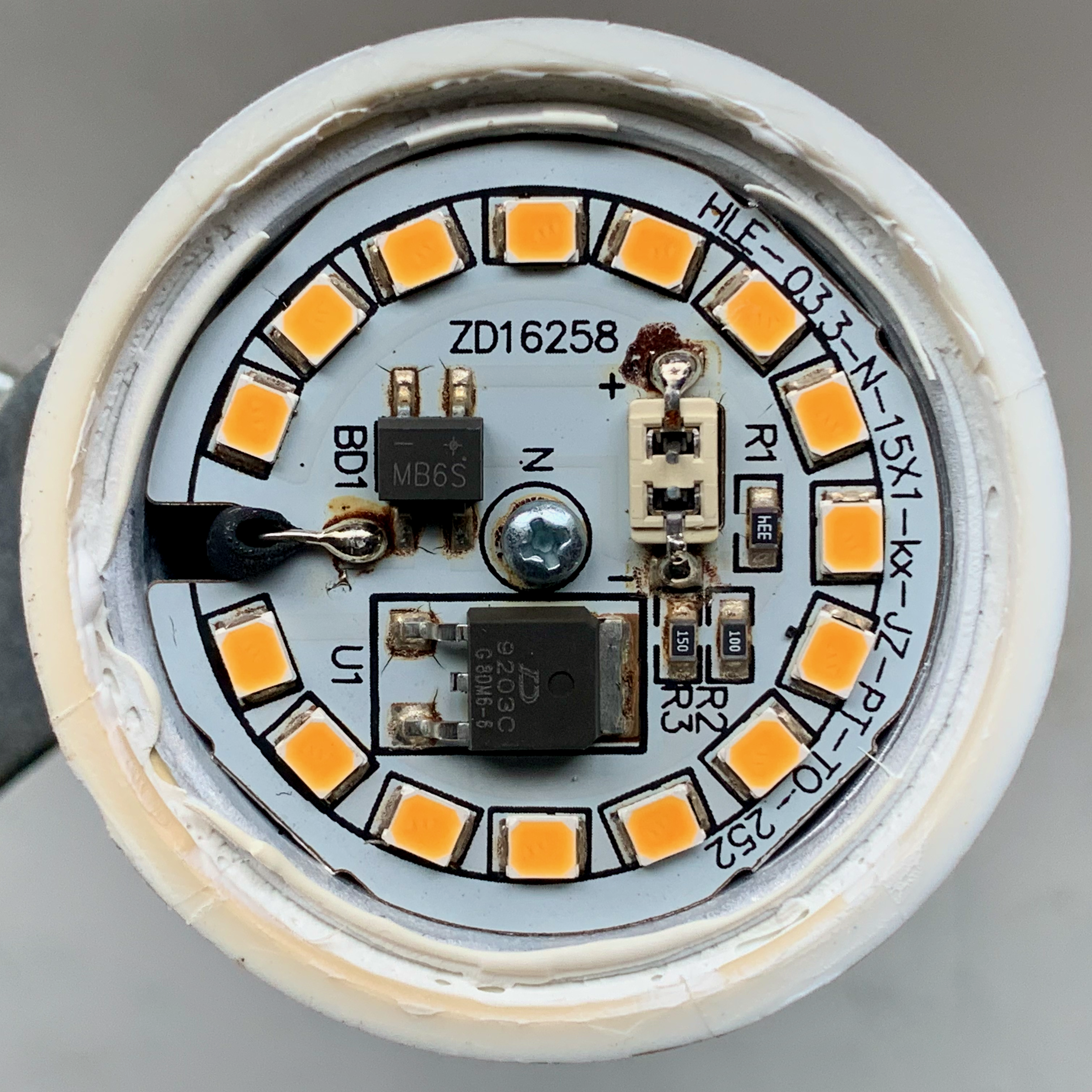
The circuit board itself was aluminum and was bonded to an aluminum sheet wrapped around the interior of the housing. This appears to be for the purpose of maximizing heat disipation. The aluminum base was covered with a non-conductive film. The copper traces between components were then placed on top of this. The capacitor (the only through-hole component) used a plastic shim to keep it in place and prevent it from shorting against the aluminum layer of the board.
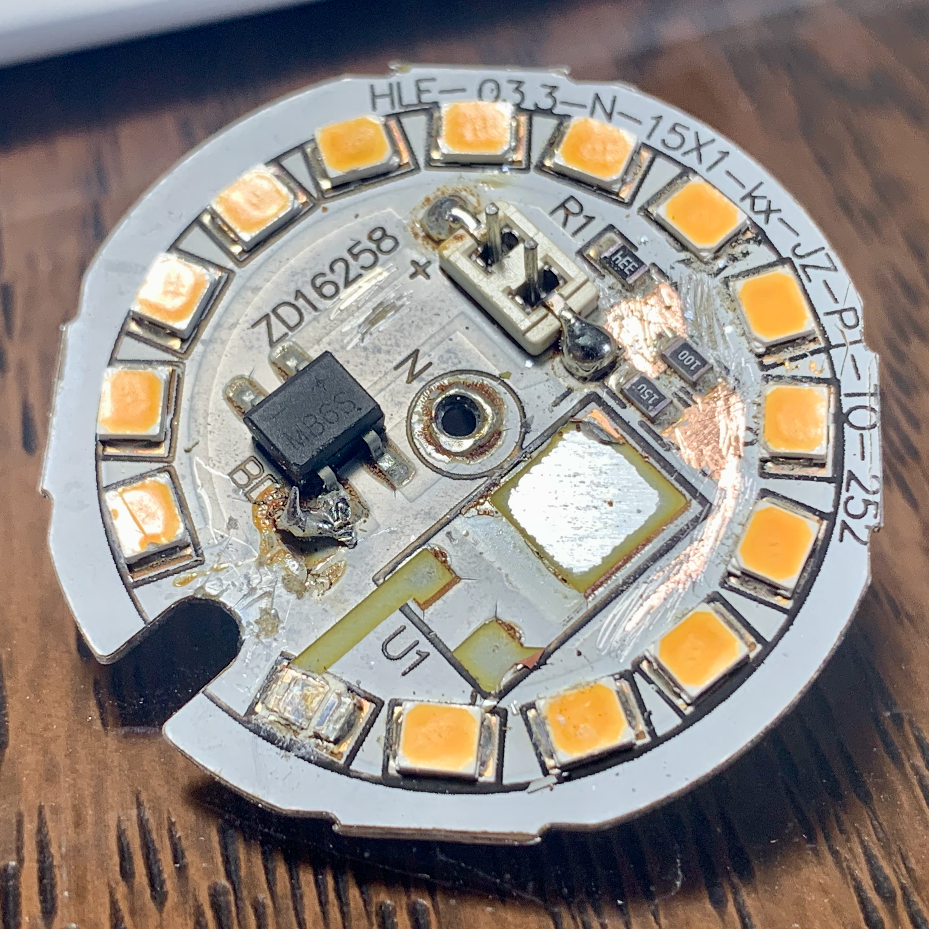
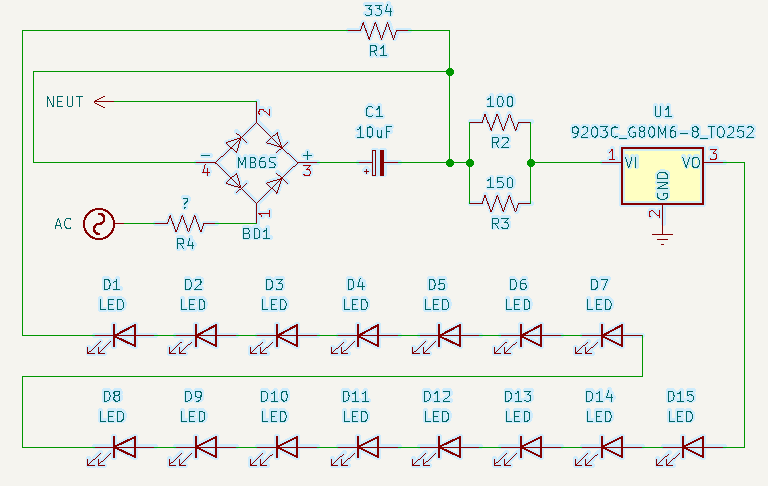
I was rather surprised by the simplicity of the circuit design. A few resistors, a capacitor, a bridge rectifier, a circular chain of fifteen SMD white LEDs, and what I believe is a linear regulator. The linear regulator and the LEDs were the only components I couldn’t positively identify from their markings.
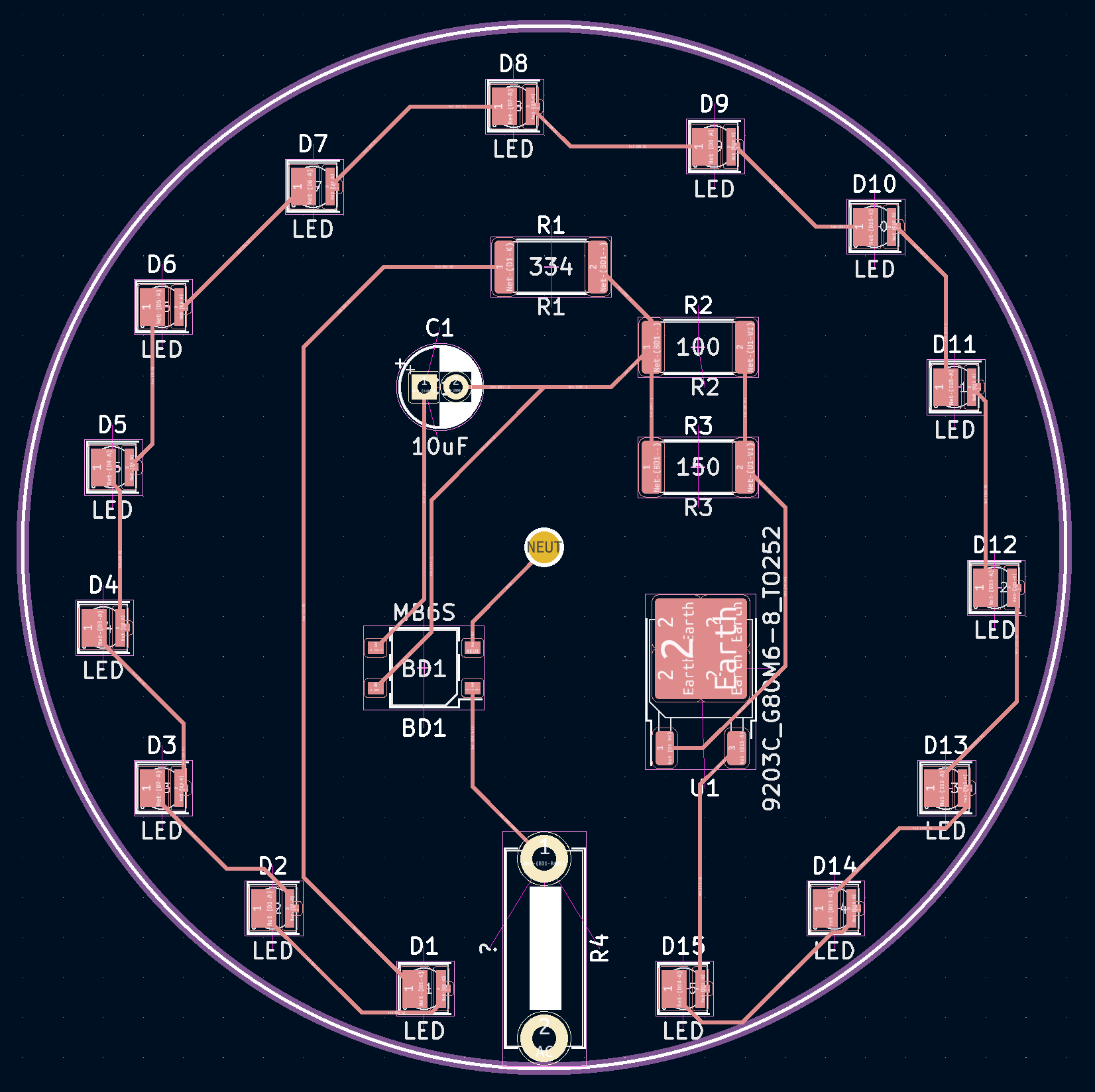
After inspecting the board, researching the components, and doing a bit of probing to confirm my thoughts, I used KiKAD to put together a close approximation. PDFs of the schematic and PCB are linked below.
Schematic
PCB